Forming method of bionic porous structure with hydrophobic resistance reducing capability
A porous structure and forming method technology, applied in the field of metal surface treatment, can solve the problems of poor stability of the micro-nano bionic embossed structure, easy damage or even disappear of the embossed structure, difficulty in maintaining super-hydrophobic performance, etc., and achieve good lodging resistance , Excellent hydrophobic effect, good structural stability
- Summary
- Abstract
- Description
- Claims
- Application Information
AI Technical Summary
Problems solved by technology
Method used
Image

Examples
Embodiment 1
[0036] (1) Add the solute ethylene glycol sulfate and ammonium fluoride into the solvent deionized water to fully dissolve and stir evenly to obtain an anodic oxidation solution, in which the concentration of the solute is 30-50mL / L of ethylene glycol sulfate and 13g / L of ammonium fluoride ;
[0037] (2) The surface of the TC4 titanium alloy sample is degreased with a degreasing agent and then cleaned with deionized water. It is connected to the positive electrode of the anodized power supply, and the stainless steel plate is used as the cathode plate to connect to the negative electrode of the power supply. In the anodizing solution, turn on the anodizing power supply, gradually increase the oxidation voltage to 40V, and the oxidation time is 1h. During the oxidation process, the temperature of the solution is controlled at about 20°C by the chiller. After oxidation, turn off the oxidation power, rinse the sample with deionized water, and dry it with clean compressed air.
...
Embodiment 2
[0043] (1) Pre-polishing the surface of 5083 aluminum alloy to obtain the test sample after surface polishing. Put the polished 5083 aluminum alloy sample into deionized water for ultrasonic cleaning for 5 minutes, and then blow dry to obtain a 5083 aluminum alloy sample with a clean surface;
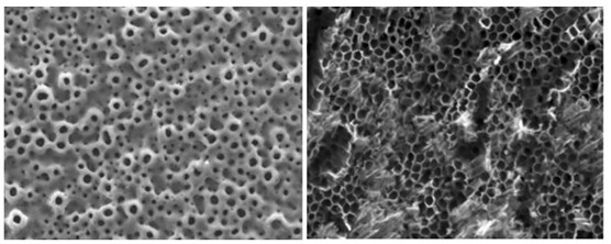
[0044] (2) The femtosecond ultrafast laser is used to complete the periodic hole preparation of 5083 aluminum alloy. The laser processing parameters are as follows: the laser wavelength is 1030nm, the laser power is 13W, the laser pulse frequency is 30kHz, the beam scanning speed is 200mm / s, the scanning path is linear scanning, and the scanning distance is 60μm.
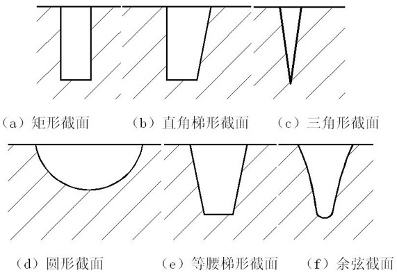
[0045] (3) Inject low free energy substances such as silane or halothane coupling agent into the surface groove of the sample to obtain a surface biomimetic groove structure with superhydrophobic drag reduction capability.
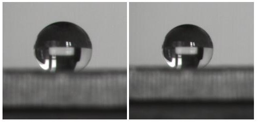
[0046] (4) The surface wetting angle of 5083 aluminum alloy with smooth surface is 52.62°, and the ma...
PUM
 Abstract
Description
Claims
Application Information