Optical transceiver module assembling method

A technology of optical transceiver components and assembly methods, which is applied to the coupling of optical elements, optical waveguides, light guides, etc., can solve the problems of low assembly and matching efficiency, unobjective evaluation criteria for the assembly process of optical transceiver components, etc., and achieve the effect of accurate assembly positioning

Active Publication Date: 2017-02-01
HISENSE BROADBAND MULTIMEDIA TECH
View PDF7 Cites 6 Cited by
  • Summary
  • Abstract
  • Description
  • Claims
  • Application Information

AI Technical Summary

Problems solved by technology

[0008] The invention provides a method for assembling optical transceiver components, which can solve the problems of unobjective evaluation criteria and low assembly matching efficiency of optical transceiver components, reduce production difficulty and improve production efficiency

Method used


Image

  • Optical transceiver module assembling method
  • Optical transceiver module assembling method
  • Optical transceiver module assembling method

Examples


no. 1 example

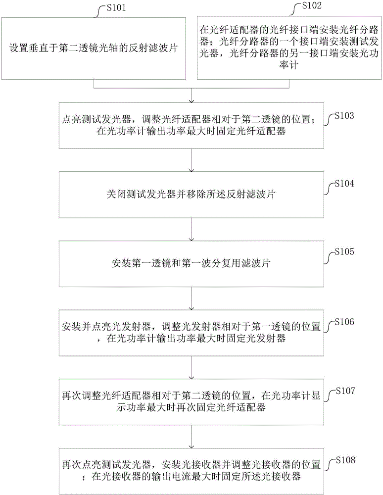
[0037] image 3 It is a flow chart of the method for assembling the optical transceiver assembly in the first embodiment. Such as image 3 , The method for assembling the optical transceiver assembly in the first embodiment includes the following steps.

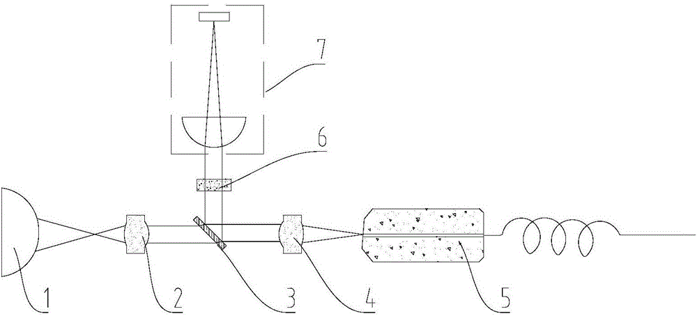
[0038] S101: setting the reflective filter 8 perpendicular to the optical axis of the second lens 4 .

[0039] S102: Install a fiber optic splitter 9 at the fiber interface end of the fiber optic adapter 5; install a test light emitter 10 at one interface end of the fiber optic splitter 9, and install an optical power meter 11 at the other interface end of the fiber optic splitter 9.

[0040] Figure 4 is a schematic diagram of positioning the fiber optic adapter in the first embodiment, such as Figure 4 , the optical fiber splitter 9 is installed on the optical fiber interface end of the optical fiber adapter 5, and is connected with the optical fiber adapter 5 through an optical fiber. One interface end of the optical...

no. 2 example

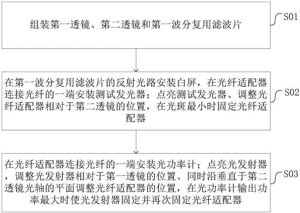
[0057] Image 6 It is a flow chart of the method for assembling the optical transceiver assembly in the second embodiment. Such as Image 6 , The method for assembling the optical transceiver assembly in the second embodiment includes the following steps.

[0058] S201: Assemble the first lens 2, the second lens 4 and the first wavelength division multiplexing filter 3.

[0059] In this embodiment, the first lens 2, the second lens 4 and the first wavelength division multiplexing filter 3 are fixed by mechanical positioning to form the first assembly, wherein the light parallel to the optical axis of the first lens 2 passes through the first wavelength division After the filter 3 is multiplexed, it is parallel to the optical axis of the second lens 4 .

[0060] S202: Install an optical fiber splitter 9 at the optical fiber interface end of the optical fiber adapter 5, install a test light emitter 10 for emitting test light at one interface end of the optical fiber splitter ...


PUM


Abstract

The invention provides an optical transceiver module assembling method. The method comprises the following steps: a reflection filter vertical to the optical axis of a second lens is arranged; an optical fiber splitter is arranged at an optical fiber interface end of an optical fiber adapter, one interface end of the optical fiber splitter is provided with a test illuminator, and the other interface end of the optical fiber splitter is provided with an optical power meter; if test light emitted by the test illuminator passes through the second lens and is then parallel with the optical axis of the second lens, the reflection filter totally reflects the test light; the test illuminator is turned on, the position of the optical fiber adapter relative to the second lens is adjusted, and the optical fiber adapter is fixed when the output power of the optical power meter is maximum; the test illuminator is turned off and the reflection filter is removed; a first lens and a first wavelength division multiplexing filter are arranged; and a light emitter is arranged and turned on, the position of the light emitter in relative to the first lens is adjusted, and the light emitter is fixed when the output power of the optical power meter is maximum.

Description

technical field [0001] The invention relates to the technical field of optical fiber communication, in particular to an assembly method of an optical transceiver assembly. Background technique [0002] The optical transceiver component is the working part that realizes the conversion of optical signal and electrical signal in the optical fiber communication system, and is one of the core components of the optical fiber communication system. figure 1 It is a structural schematic diagram of an optical transceiver component in the prior art. Such as figure 1 , an optical transceiver assembly in the prior art includes an optical transmitter 1 , a first lens 2 , a first wavelength division multiplexing filter 3 , a second lens 4 , an optical fiber adapter 5 and an optical receiver 7 . The first lens 2 is installed between the optical transmitter 1 and the first wavelength division multiplexing filter 3, and is used to convert the upstream optical signal emitted by the optical t...

Claims


Application Information

Patent Timeline
IPC IPC(8): G02B6/42
CPCG02B6/4225G02B6/4227
Inventor 蔚永军宋琛
Owner HISENSE BROADBAND MULTIMEDIA TECH
Why Eureka
Try Eureka