Installation structure of train roof jumper cable of urban rail

A technology for jumping cables and installation structures, which is applied in the installation of cables, cable arrangement between relatively moving parts, electrical components, etc., can solve the problems of large frame space, low work efficiency, long cable paths, etc. Simple environment, small footprint, and short cable paths

Active Publication Date: 2017-02-01
CRRC DALIAN CO LTD
View PDF5 Cites 27 Cited by
  • Summary
  • Abstract
  • Description
  • Claims
  • Application Information

AI Technical Summary

Problems solved by technology

[0006] (1) It is greatly affected by the vehicle limit, and it is easy to collide with sundries on the track, or scratch during maintenance and disassembly;
[0007] (2) Close to the ground, subject to long-term chronic corrosion such as gravel, dust and water, the jumper cables and their components have high protection requirements and high costs;
[0008] (3) The surrounding steel structure environment is complex, and the turning process is easy to wear with the small parts of the chassis;
[0009] (4) The jumper wires need to be divided in the distribution box under the vehicle, the cable path is long, and the maintenance operation of the wiring under the vehicle is very inconvenient and the work efficiency is low;
[0010] (5) There is no support in the middle of the jumper cable, which is subjected to gravity for a long time, and the cable life cycle is short;
[0011] (6) The connector is subject to the pulling force from the cable for a long time, and it is easy to loosen and damage, posing a great safety hazard;
[0012] (7) The junction box and jumper wires are large in size and take up a lot of space on the frame
[0015] (1) The end wall structure must be specially designed, and the arrangement of other parts at the end must be coordinated, which requires a large workload;
[0016] (2) Limited by the distance between vehicles, the scope of application is small
[0017] (3) The structure of the through-channel needs to be specially customized, the cost is high, and the interface and wiring space need to be reserved, and the available passing space of the corresponding through-channel is reduced;
[0018] (4) Due to space constraints, electrical boxes cannot be arranged, and all cables are collected on the top of the end wall, and the cables are exposed, which poses a safety hazard and is inconvenient for later inspection and maintenance;
[0019] (5) The jumper cable is hidden inside the through passage, so it is difficult to be found if the connection wear occurs, and there is a hidden danger of leakage;
[0020] (6) The installation and operation space is narrow, and the installation and maintenance efficiency is low;
[0021] (7) The high-voltage cable connection part is located on the end wall of the passenger compartment, which poses a safety hazard to passengers in the passenger compartment;
[0023] (9) The connector is subject to the pulling force from the cable for a long time, and it is easy to loosen and damage, posing a great safety hazard;
[0024] In recent years, with the diversification of urban rail vehicle models and marshalling methods, more and more urban rail vehicles adopt articulated bogie structure, and the corresponding vehicle structure has also undergone major changes, and jumper cables cannot be arranged on the vehicle chassis
At the same time, the previous jumper methods were affected by factors such as complex environments, vehicle boundaries, gravity factors, equipment layout, and operating space, resulting in strict requirements for the protection level of jumper cables and their accessories, long wiring paths, small operating spaces, and short life cycles. There are great potential safety hazards, and the end walls and through passages need to be specially customized, resulting in increased equipment procurement costs and labor costs, and low installation and maintenance efficiency.

Method used


Image

  • Installation structure of train roof jumper cable of urban rail
  • Installation structure of train roof jumper cable of urban rail
  • Installation structure of train roof jumper cable of urban rail

Examples


Embodiment

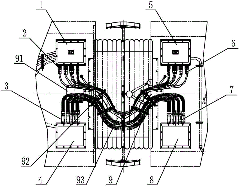
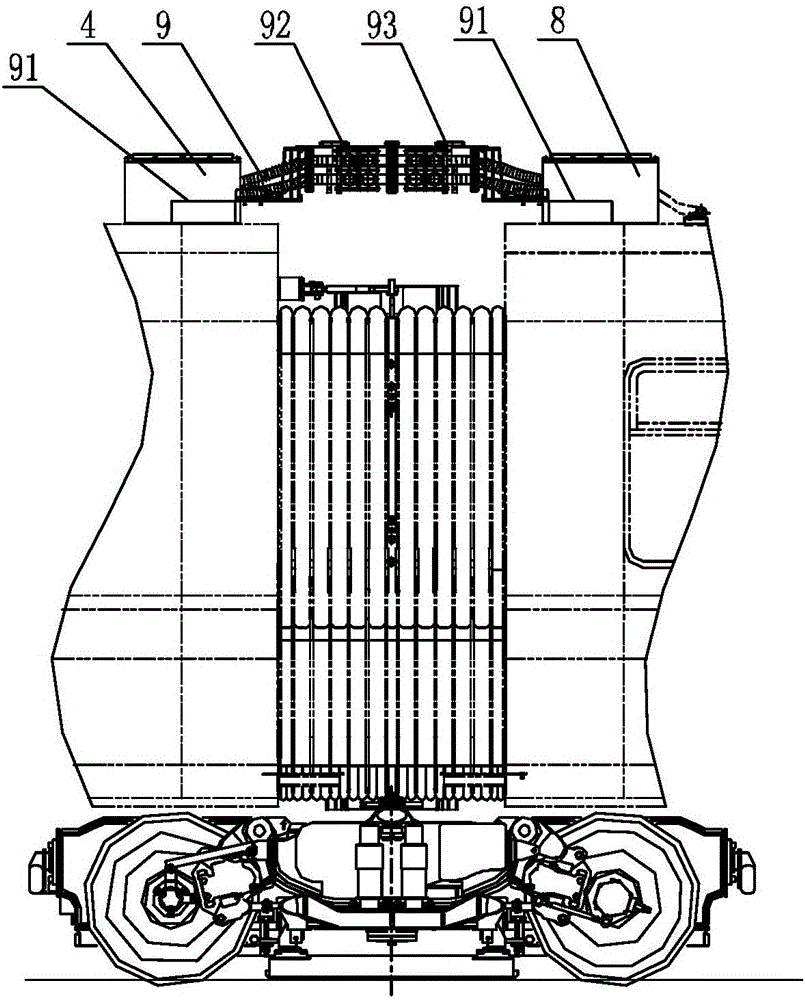
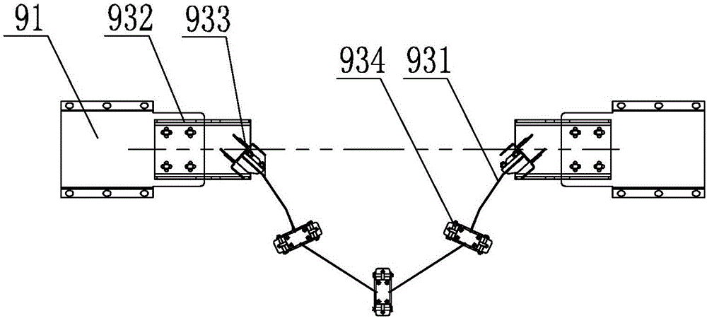
[0081]Embodiment: According to the marshalling mode and structural characteristics of the train, two sets of roof jumper cable systems are used. Due to the reversing of the vehicle circuit, in order to ensure that the length of the high and low voltage cables remains uniform, the jumper cable 9 and the dynamic flexible wiring frame 93 are installed in reverse, the high-voltage connector box 1, the high-voltage connector box 2 5, and the low-voltage connector box 14. Low-voltage connector box 2 8 cross layout, the whole train is composed of two different sets of roof jumper cable systems, the first set of roof jumper cable system consists of high-voltage connector box 1, high-voltage connector box 2 5 , low-voltage connector box one 4, low-voltage connector box two 8, 9 sets of jumper cables 9, a dynamic flexible wiring rack 93, 10 sets of clamping plates 92, 2 protective support mounting seats 91, high and low voltage connectors 1 2. High and low voltage connector two 3, high ...


PUM


Abstract

The invention discloses an installation structure of a train roof jumper cable of the urban rail. A first high-voltage connector casing, a first high/low voltage connector, a second high/low voltage connector and a first low-voltage connector casing are positioned in the top of a first compartment; a second high-voltage connector casing, a third high/low voltage connector, a fourth high/low voltage connector and a second low-voltage connector casing are positioned in the top of a second compartment; the first high/low voltage connector on the first high-voltage connector casing is connected to the third high/low voltage connector on the second high-voltage connector casing via the jumper cable; and the second high/low voltage connector on the first low-voltage connector casing is connected with the fourth high/low voltage connector on the second low-voltage connector casing via the jumper cable. The installation structure has the advantages that the operation space is large, the installation environment is simple, and the structure is safer and more reliable; the service life is longer; the cable path is shorter, and the cost is reduced greatly; the sealing performance is higher; the whole installation structure can be dismounted rapidly, the occupation space is small, and the structure is beautiful and tidy; and it is not required to reconstruct end wall and channel structures, the workload is low, and the cost is lower.

Description

technical field [0001] The invention relates to a cable installation structure, in particular to an urban rail vehicle roof jumper cable installation structure. Background technique [0002] The jumper cable is an important part to realize the electrical connection between multiple groups of urban rail vehicles. The function of the jumper cable is to realize the power transmission of the main circuit of the vehicle, the transmission of control signals, the transmission of network signals and the equal potential of the negative pole of the circuit. The jumper circuit is located at the connecting part of the two carriages. During the operation of the vehicle, auxiliary stress and special working conditions (such as too small a curve radius, too large impact rate, etc.) will have a major impact on the safety of the jumper circuit. Long-term complex stress effects will affect the fatigue life and weather resistance of jumper cables. In special working conditions, such as curve...

Claims


Application Information

Patent Timeline
Patent Type & Authority Applications(China)
IPC IPC(8): H02G3/00H02G3/04H02G3/08H02G11/00
CPCH02G3/00H02G3/04H02G3/088H02G11/003
Inventor 刘秀美王尔为吴英帅丁锋李亮郭涛
Owner CRRC DALIAN CO LTD
Why Eureka
Try Eureka