Step level output circuit

A technology of output circuit and level, applied in the direction of logic circuit, logic circuit connection/interface layout, electrical components, etc., can solve the problems of low conduction resistance, low cost performance, etc., achieve fast output response, improve cost performance, and maintain small current Effect

Active Publication Date: 2017-02-01
CRM ICBG (WUXI) CO LTD
View PDF4 Cites 0 Cited by
  • Summary
  • Abstract
  • Description
  • Claims
  • Application Information

AI Technical Summary

Problems solved by technology

The response speed of this structure is better than that of method 1, but because the V1 generated by the voltage source circuit needs a strong driving capability, the output tube of the voltage source circuit needs to be made larger, and the switch tubes P31, P32 and N32 also need Low on-resistance, so this structure requires a large area of ​​output transistors to meet the requirements of the drive output, and the cost performance is very low

Method used


Image

  • Step level output circuit
  • Step level output circuit
  • Step level output circuit

Examples


Embodiment Construction

[0027] In order to be able to describe the technical content of the present invention more clearly, further description will be given below in conjunction with specific embodiments.

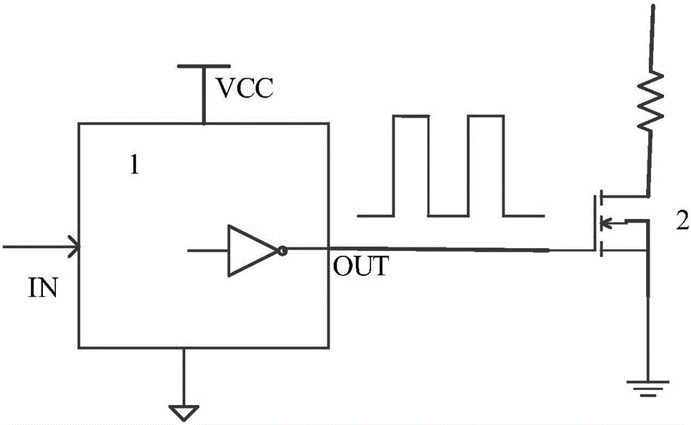
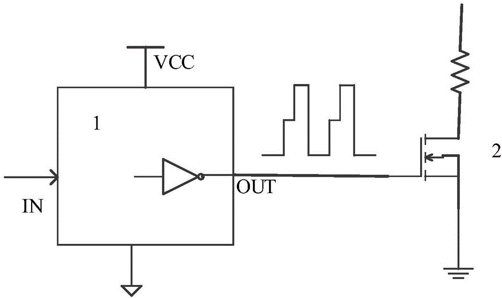
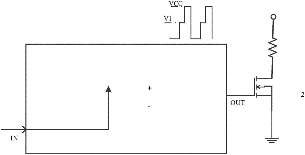
[0028] The present invention provides a step-level output circuit for providing a stepped voltage for the gate of a power element. In a feasible implementation, the step-level output circuit includes a reference source circuit, an intermediate A level drive circuit, a control circuit, a first P-type transistor, a first N-type transistor and a second N-type transistor, the reference source circuit outputs a reference level signal to the intermediate level drive circuit, The first control terminal and the first inverting control terminal of the control circuit are respectively connected to the intermediate level drive circuit, and the second control terminal of the control circuit is connected to the gate of the first P-type transistor. Connected, the third control terminal of the control circuit is c...


PUM


Abstract

The invention relates to a step level output circuit, comprising a reference source circuit, an intermediate level drive circuit, a control circuit, a first P type transistor, a first N type transistor and a second N type transistor. The intermediate level drive circuit comprises a current source, a second P type transistor, a third N type transistor and a capacitor. A threshold voltage Vthp of the second P type transistor, the threshold voltage Vthn of the second N type transistor, an intermediate voltage V1 output by an output end of the step level output circuit and a reference voltage VF output by the reference source circuit have the following relationship: VF=V1+Vthn-Vthp. Through adoption of the circuit of the structure, the output response is fast, the circuit is applicable to bandwidth application of a wide range, the structure is concise, a maintenance current is low, only three drive tubes are required, an area of a chip is reduced, a cost performance ratio is improved, and moreover, the fast response feature is kept, and the application range is wide.

Description

Technical field [0001] The present invention relates to the technical field of gate driving, in particular to the technical field of step-level gate driving, in particular to a step-level output circuit. Background technique [0002] In the driving circuit, especially in the driving of the IGBT, the driving IC is usually used to generate a pulse voltage to drive the gate of the IGBT, such as figure 1 As shown, in some applications, the driver IC sometimes needs to generate a step level to drive the IGBT (or MOS tube), such as figure 2 Shown. The driving IGBT (or MOS tube) signal rises to a set level first, and then jumps to the VCC level after a period of time. [0003] There are usually two ways to achieve the above functions: [0004] Implementation method one, such as image 3 As shown, the reference source module outputs a reference voltage V1, and the op amp is used in a follower mode. The input reference voltage signal at the forward end of the op amp is switched by a switch,...

Claims


Application Information

Patent Timeline
Patent Type & Authority Applications(China)
IPC IPC(8): H03K19/0185
CPCH03K19/018507
Inventor 刘卫中程学农郁一峰
Owner CRM ICBG (WUXI) CO LTD
Why Eureka
Try Eureka