Power carrier signal coupling circuit and communication system

A technology of signal coupling and power carrier, applied in power line communication systems, systems using coupling circuits, power line communication applications, etc., can solve the problem of high cost, and achieve the effect of reducing installation complexity and cost

Inactive Publication Date: 2017-02-01
SUNGROW POWER SUPPLY CO LTD
View PDF5 Cites 6 Cited by
  • Summary
  • Abstract
  • Description
  • Claims
  • Application Information

AI Technical Summary

Problems solved by technology

This method requires multiple carrier modulation circuits and receiving devices, and the cost is also high

Method used


Image

  • Power carrier signal coupling circuit and communication system
  • Power carrier signal coupling circuit and communication system
  • Power carrier signal coupling circuit and communication system

Examples


Embodiment 1

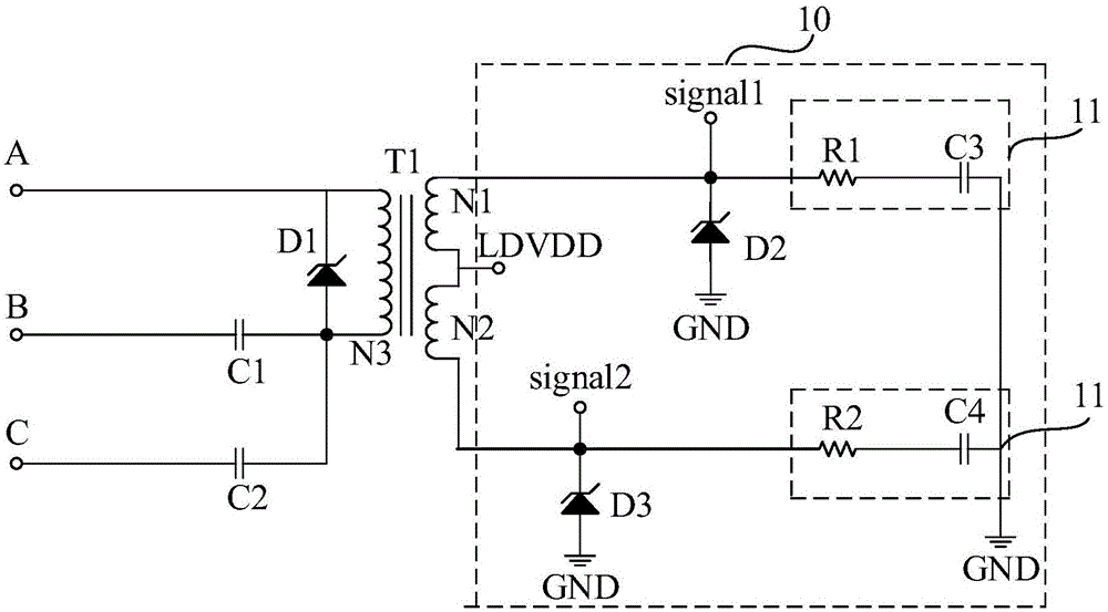
[0044] Embodiment 1, the power carrier signal coupling circuit includes a first transient suppression diode D1, the A phase of the power cable is a common channel, and the first power carrier signal coupling channel is set between the B phase of the power cable and the phase B of the power cable. Between phase A, the second power carrier signal coupling channel is set between phase C of the power cable and phase A of the power cable; the cathode of the first transient suppression diode D1 is connected to phase A of the power cable, The anode of the first transient suppression diode D1 is respectively connected to the B phase of the power cable and the C phase of the power cable.

Embodiment 2

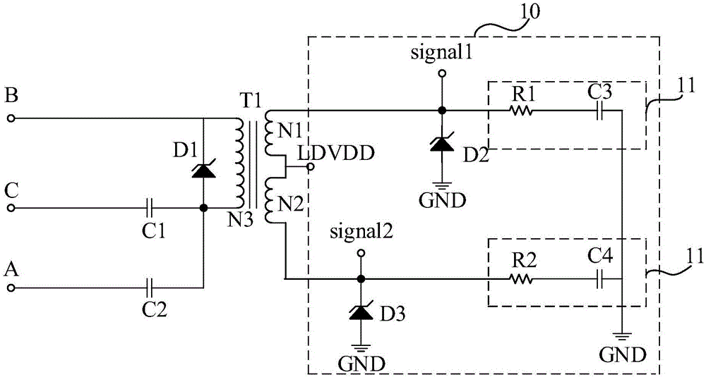
[0045] Embodiment 2, the power carrier signal coupling circuit further includes a first transient suppression diode D1, the B phase of the power cable is a common channel, and the first power carrier signal coupling channel is set between the A phase of the power cable and the power cable Between phase B of the power cable, the second power carrier signal coupling channel is set between phase C of the power cable and phase B of the power cable; the cathode of the first transient suppression diode D1 is connected to phase B of the power cable , the anode of the first transient suppression diode D1 is respectively connected to the A phase of the power cable and the C phase of the power cable.

Embodiment 3

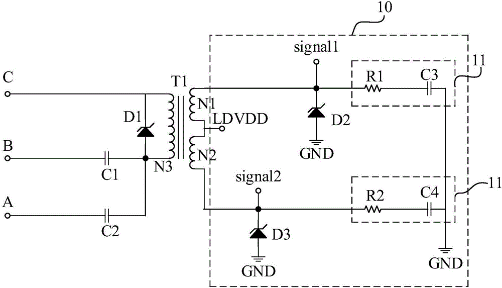
[0046] Embodiment 3, the power carrier signal coupling circuit further includes a first transient suppression diode D1, the C phase of the power cable is a common channel, and the first power carrier signal coupling channel is set between the A phase of the power cable and the power cable Between phase C of the power cable, the second power carrier signal coupling channel is set between phase B of the power cable and phase C of the power cable; the cathode of the first transient suppression diode D1 is connected to phase C of the power cable , the anode of the first transient suppression diode D1 is respectively connected to the A phase of the power cable and the B phase of the power cable.


PUM


Abstract

The present invention discloses a power carrier signal coupling circuit and a communication system. The power carrier signal coupling circuit comprises a first power carrier signal coupling channel and a second power carrier signal coupling channel. Any phase of three phases of alternating current power cable is used as a public channel. The first power carrier signal coupling channel is disposed between another phase of power cable and the public channel. The second power carrier signal coupling channel is disposed between the last phase of power cable and the public channel. Through adoption of the method, the reliability of the power carrier communication is improved, and the communication cost is lowered.

Description

technical field [0001] The invention relates to the technical field of power carrier communication, in particular to a power carrier signal coupling circuit and a communication system. Background technique [0002] PLC (Power line Communication, power carrier communication) has become the preferred communication method for the power system communication network due to the rich user resources and economic benefits of the distribution network. [0003] However, the power line channel is not an ideal channel. The noise interference on the power line is serious, the load conditions are changeable, and the channel parameters are also affected by time, location, frequency and devices connected to it, and there is a problem of low reliability. [0004] In order to improve reliability, one method in the prior art is to connect the power line carrier master and slave equipment in parallel through inductance or capacitance, and couple them between the three-phase line and the neutral ...

Claims


Application Information

Patent Timeline
Patent Type & Authority Applications(China)
IPC IPC(8): H04B3/56
CPCH04B3/56H04B2203/5483H04B2203/5466Y04S40/121Y02E60/00H02J13/00009H04B2203/5437H04B2203/5445H04L12/2803H04L12/2838
Inventor 翟寄文戴云海方良书郝竹青常艳芬
Owner SUNGROW POWER SUPPLY CO LTD
Why Eureka
Try Eureka