A system for calibrating the transmit and receive channels of tr components through antenna spatial coupling

A transceiver channel and space coupling technology, applied in receiver monitoring, transmitter monitoring, etc., can solve problems such as ineffective weight reduction and complicated wiring

Active Publication Date: 2018-11-30
DFINE TECH
View PDF7 Cites 0 Cited by
  • Summary
  • Abstract
  • Description
  • Claims
  • Application Information

AI Technical Summary

Problems solved by technology

[0002] The traditional TR antenna front-end uses buried coupling lines in each radiating unit, and enters the calibration transceiver channel through the coupling lines. This calibration method has complex circuits and cannot effectively reduce weight.

Method used


Image

  • A system for calibrating the transmit and receive channels of tr components through antenna spatial coupling
  • A system for calibrating the transmit and receive channels of tr components through antenna spatial coupling
  • A system for calibrating the transmit and receive channels of tr components through antenna spatial coupling

Examples


Embodiment Construction

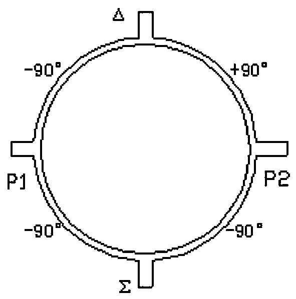
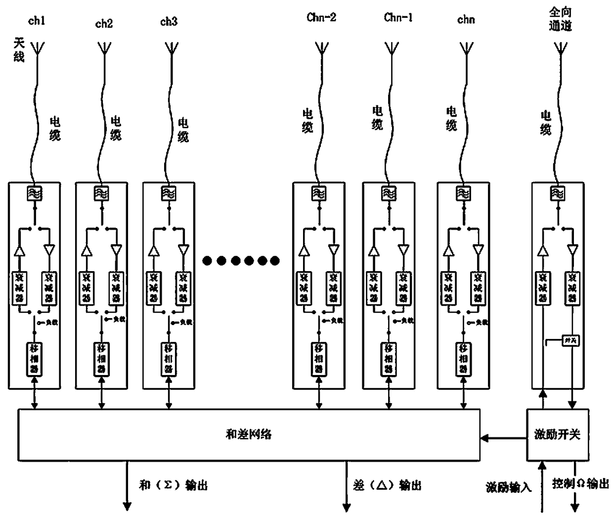
[0062] 1.1 The TR module is switched by a switch, and the excitation signal is input to the sum and difference network, and the power is divided into CH1~CHn by the sum and difference network, and then transmitted from the antenna after amplification and filtering.

[0063] The 1.2TR module is switched by a switch, and the excitation signal is input to the Ω channel, and then transmitted from the antenna after amplification and filtering.

[0064] 1.3TR module filters, amplifies, and synthesizes the signal received by the antenna to form a sum and difference signal and outputs it to the back-end receiver.

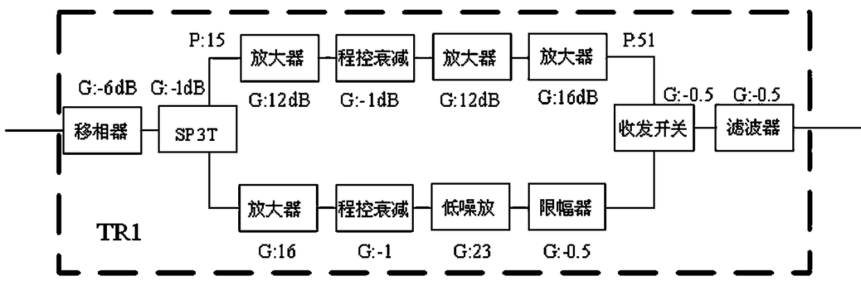
[0065] A system for calibrating the transceiver channels of TR components through spatial coupling between antennas, characterized in that the sum and difference network is respectively connected to several antennas CH1~CHn through the TR1-TRn component transceiver channels, and the TR component transceiver channels are controlled by phase shifters, SP3T, and program Attenu...


PUM


Abstract

The invention discloses a system for calibrating a TR component transceiving channel through antenna spatial coupling. Due to a mode of realizing calibration by burying coupling lines on antennas, the weight of the system can be greatly reduced, and the complexity is reduced. A sum-difference network is connected with a plurality of transceiving channels; the transceiving channels are connected to the antennas through cables. Each transceiving channel can be independently controlled, and consists of a phase shifter, an attenuator, an amplifier and a filter; and sum and difference outputs of the sum-difference network are connected with a rear-end receiver.

Description

Technical field: [0001] The present invention relates to an amplitude and phase calibration system for a transceiver channel of a receiver. Background technique: [0002] The traditional TR antenna front-end uses a coupling line buried in each radiating unit, and enters the calibration transceiver channel through the coupling line. This calibration method has complicated circuits and cannot effectively reduce weight. Invention content: [0003] The purpose of the present invention is to provide a system with simple structure, small workload, less data volume, and accurate calibration data through spatial coupling between antennas to calibrate the transmission and reception channels of TR components. [0004] The present invention is achieved like this: [0005] A system for calibrating the transceiver channels of TR components through spatial coupling between antennas, characterized in that the sum and difference network is respectively connected to several antennas CH1~C...

Claims


Application Information

Patent Timeline
Patent Type & Authority Patents(China)
IPC IPC(8): H04B17/12H04B17/21
CPCH04B17/12H04B17/21
Inventor 谭尊林张敏
Owner DFINE TECH
Why Eureka
Try Eureka