Forming method of jaw part of machine tool piece

A technology for parts and machine tools, which is applied in the forming field of the jaw parts of machine tools, can solve problems such as uneven wall thickness, sand/slag inclusions, etc., and achieve the effects of reducing operation difficulty, avoiding casting defects, and optimizing the process

Active Publication Date: 2017-02-08
NINGXIA KOCEL MOLD
View PDF6 Cites 2 Cited by
  • Summary
  • Abstract
  • Description
  • Claims
  • Application Information

AI Technical Summary

Problems solved by technology

[0005] In view of the problems existing in the related art, the object of the present invention is to provide a forming method for the jaws of machine tool parts, so as to prevent casting defects such as sand / slag inclusions and uneven wall thickness in the jaws of machine tool parts, and improve the quality of castings

Method used


Image

  • Forming method of jaw part of machine tool piece
  • Forming method of jaw part of machine tool piece
  • Forming method of jaw part of machine tool piece

Examples


Embodiment Construction

[0023] Embodiments of the present invention will be described in detail below in conjunction with the accompanying drawings.

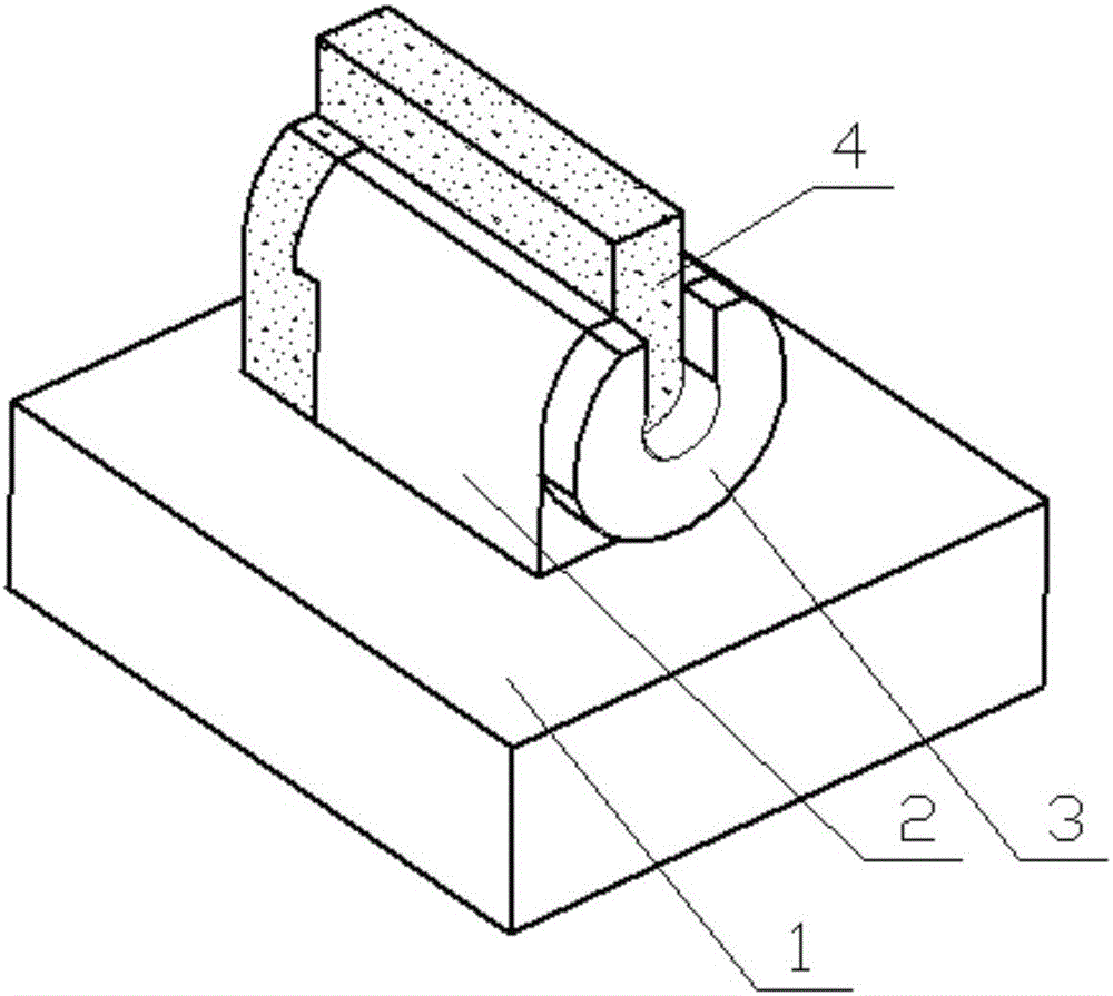
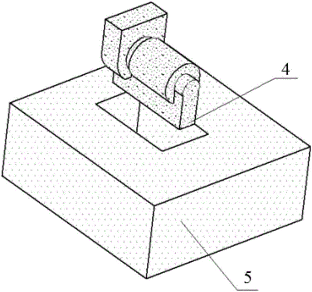
[0024] Such as Figure 3 to Figure 5 As shown, one embodiment of the present invention provides a kind of forming method of jaw part of machine tool, comprising:

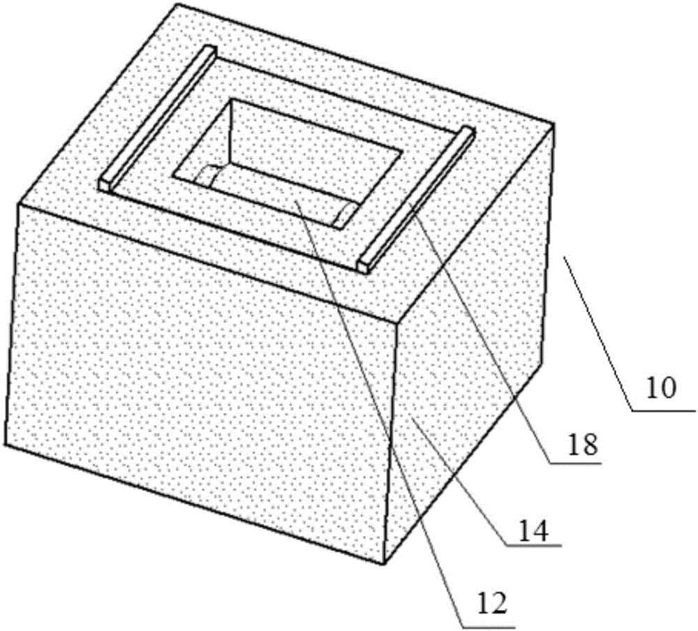
[0025] S1: A sand core 10 is formed by 3D printing, and the sand core 10 is composed of a jaw sand core structure 12 and a sand core outer mold 14 formed outside the jaw sand core structure to jointly form the jaw part to be cast;

[0026] S2: installing the sand core 10 to the sand mold pattern 16, and placing the sand core 10 and the sand mold pattern 16 in the sand box for sand filling; and

[0027] S3: Demoulding the sand mold pattern 16 and performing casting.

[0028] In the above embodiment, the sand core 10 composed of the jaw sand core structure 12 and the sand core outer mold 14 formed outside the jaw sand core structure 12 to jointly form the jaw part to be cast is printed by 3D...


PUM


Abstract

The invention provides a forming method of a jaw part of a machine tool piece. The forming method of the jaw part of the machine tool piece comprises the steps of forming a sand core through 3D (three dimensional) printing, wherein the sand core is formed by a jaw sand core structure and a sand core outer mold formed on the outer part of the jaw sand core structure so as to jointly form the jaw part to be cast; installing the sand core into a sand mold sample, placing the sand core and the sand mold sample into a sand box, and filling sand; and demolding the sand mold sample, and casting. According to the forming method of the jaw part of the machine tool piece provided by the invention, the casting defects such as sand inclusion and slag inclusion of the jaw part of the machine tool piece, and unevenness of wall thickness can be prevented, and the casting quality is improved.

Description

technical field [0001] The invention relates to the technical field of casting, and more specifically, to a forming method of a jaw part of a machine tool. Background technique [0002] The jaw is the main structure of machine tool castings, and it is a mechanical part that supports rotating parts and transmits motion, torque or bending moment through rotation. On the machine tool, it is connected through the shaft, the bed, the table, the saddle, etc., which has high requirements for use. Because ensuring the surface quality of the jaws during casting is a key control point in the process. [0003] The shape of jaw structure 2 is as figure 1 As shown, in the traditional casting process of the casting 1, due to its structure, the direct demoulding and material removal cannot be performed, and the inner cavity sand core 4 is required, and the demoulding material 3 is provided. Such as figure 2 As shown, the mold forms the outer contour sand mold (skin) 5, and the sand co...

Claims


Application Information

Patent Timeline
Patent Type & Authority Applications(China)
IPC IPC(8): B22C9/22B22C9/10B22C9/02
CPCB22C9/02B22C9/103B22C9/22
Inventor 苗润青
Owner NINGXIA KOCEL MOLD
Why Eureka
Try Eureka