
Movable tool main shaft device

A movable and tooling technology, applied in the direction of the chuck, etc., can solve the problems of the length of the main shaft, increase the labor intensity of the workers, bending deformation, etc., and achieve the effect of ensuring the processing accuracy, reducing the labor intensity of the workers, and convenient and quick unloading

Inactive Publication Date: 2017-02-08
成都久欣时代科技有限公司
View PDF8 Cites 0 Cited by
  • Summary
  • Abstract
  • Description
  • Claims
  • Application Information

AI Technical Summary

Problems solved by technology

However, the main shaft is long and heavy, and the bending moment on the main shaft away from the three-jaw chuck is the largest, so there is a problem of bending deformation, which affects the processing quality of the main shaft. Therefore, it is urgent to support the section far away from the three-jaw chuck.
In addition, when the unloading station is performed after processing, it is difficult to withdraw the spindle from the three-jaw chuck due to the firm fit between the three-jaw chuck and the spindle. Usually, several workers pull the spindle back together , in order to pull out the main shaft, it undoubtedly increases the labor intensity of the workers and reduces the production efficiency of the main shaft.

Method used


Image

  • Movable tool main shaft device
  • Movable tool main shaft device

Examples


Embodiment Construction

[0012] The present invention will be further described below in conjunction with accompanying drawing, protection scope of the present invention is not limited to the following:

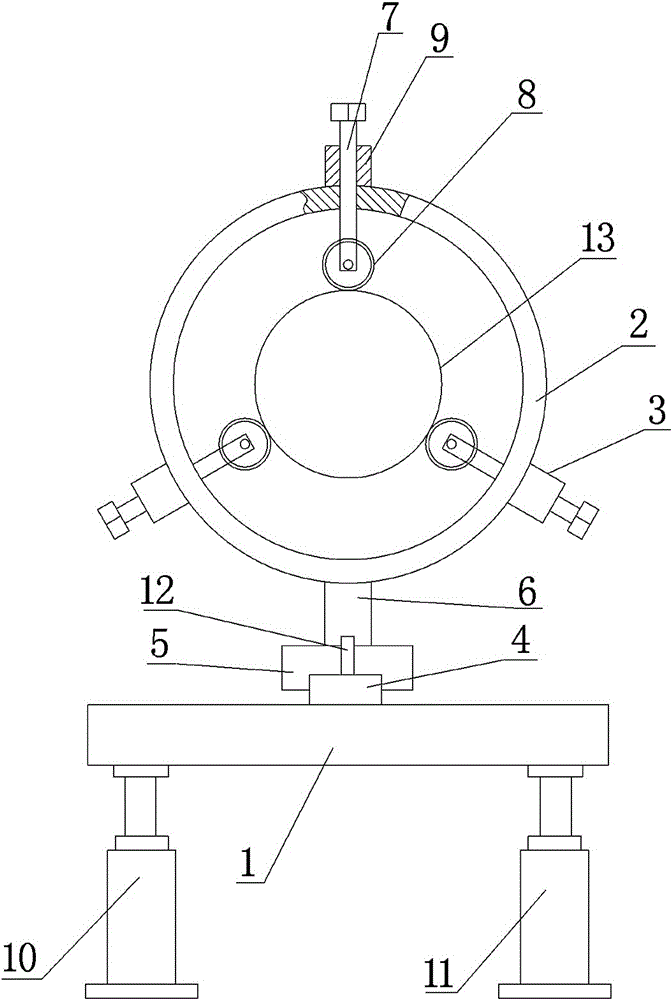
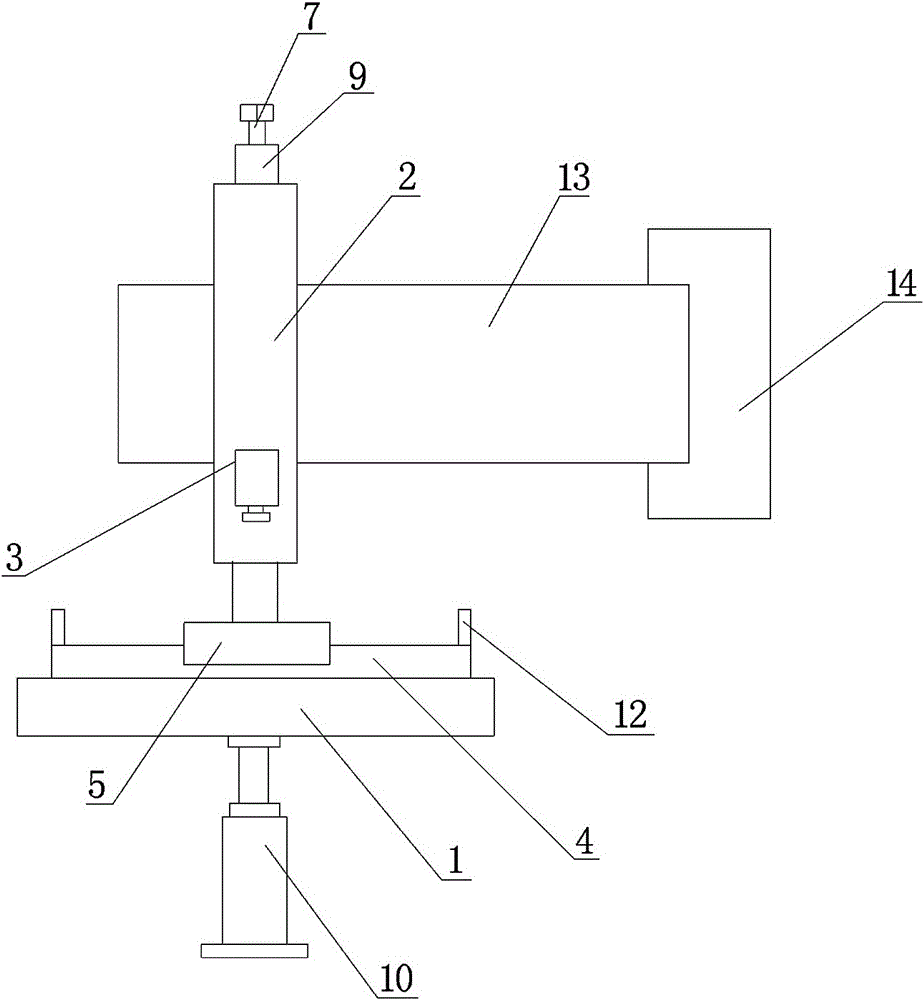
[0013] like figure 1 and figure 2 As shown, a device for a movable tooling spindle, which includes a base 1, an annular ring 2 and a clamping mechanism 3, the top of the base 1 is provided with a guide rail 4, and a guide rail 4 is installed on the guide rail 4 that can slide along the guide rail 4. The slider 5, the top of the slider 5 is provided with a fixed rod 6, the fixed rod 6 is arranged perpendicular to the top surface of the base 1, the top of the fixed rod 6 is provided with an annular ring 2, and the axis of the annular ring 2 is arranged parallel to the guide rail 4 , three clamping mechanisms 3 are evenly distributed on the outer edge of the annular ring 2, and the clamping mechanisms 3 are composed of a screw rod 7, a guide wheel 8 and a nut 9 arranged on the outer edge of the annula...


PUM


Abstract

The invention discloses a movable tool main shaft device which comprises a machine base (1), an annular ring (2) and clamping mechanisms (3). A guide rail (4) is arranged on the top of the machine base (1). The guide rail (4) is provided with a sliding block (5) capable of sliding along the guide rail (4). The three clamping mechanisms (3) are evenly distributed on the outer edge of the annular ring (2). Screw rods (7) are connected with nuts (9). The screw rods (7) are arranged in the radial direction of the annular ring (2) and penetrate the annular ring (2). A guide wheel (8) is hinged to the head portion of each screw rod (7). A perpendicular oil cylinder A (10) and a perpendicular oil cylinder B (11) are arranged at the bottom of the machine base (1). A piston rod of the perpendicular oil cylinder A (10) and a piston rod of the perpendicular oil cylinder B (11) are fixed to the machine base (1). Limiting plates (12) are arranged on the guide rail (4) and at the two end portions of the guide rail (4) correspondingly. The movable tool main shaft device has the beneficial effects that the structure is compact, the main shaft machining precision is ensured, the labor intensity of workers is lowered, and a main shaft can be conveniently and rapidly demounted.

Description

technical field [0001] The invention relates to the technical field of spindle tooling, in particular to a device for a movable tooling spindle. Background technique [0002] Shaft parts are an indispensable and important part of the transmission part. There are one or more main shafts on various machine tools, and the main shaft plays the role of transmitting power. Spindle surface grinding, turning, keyway opening and other processing all need to first install the spindle on the three-jaw chuck, and the rotation of the three-jaw chuck drives the spindle to be processed to rotate, so that the processing of the spindle can be realized. However, the main shaft is long and heavy, and the area away from the three-jaw chuck has the largest bending moment on the main shaft, so there is a problem of bending deformation, which affects the processing quality of the main shaft. Therefore, it is urgent to support the section away from the three-jaw chuck. In addition, when the unload...

Claims


Application Information

Patent Timeline
Patent Type & Authority Applications(China)
IPC IPC(8): B23B31/103B23B31/171
CPCB23B31/103B23B31/16141
Inventor 郭健辉
Owner 成都久欣时代科技有限公司
Learn More