
Clearing device of stirring machine

A technology for cleaning devices and mixers, applied to cement mixing devices, clay preparation devices, chemical instruments and methods, etc., can solve problems affecting mixing efficiency, etc., and achieve the effect of saving costs and improving efficiency

Inactive Publication Date: 2017-02-08
WUXI RISHENG CHEM CO LTD
View PDF6 Cites 9 Cited by
  • Summary
  • Abstract
  • Description
  • Claims
  • Application Information

AI Technical Summary

Problems solved by technology

[0003] The purpose of the present invention is to provide a cleaning device for a mixer, which has the advantage of scraping and cleaning the inner wall of the shell, and solves the problem that the cement solidifies on the inner wall of the shell and affects the stirring efficiency

Method used


Image

  • Clearing device of stirring machine
  • Clearing device of stirring machine

Examples


Embodiment Construction

[0016] The following will clearly and completely describe the technical solutions in the embodiments of the present invention with reference to the accompanying drawings in the embodiments of the present invention. Obviously, the described embodiments are only some, not all, embodiments of the present invention. Based on the embodiments of the present invention, all other embodiments obtained by persons of ordinary skill in the art without making creative efforts belong to the protection scope of the present invention.

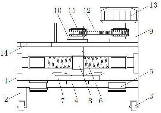
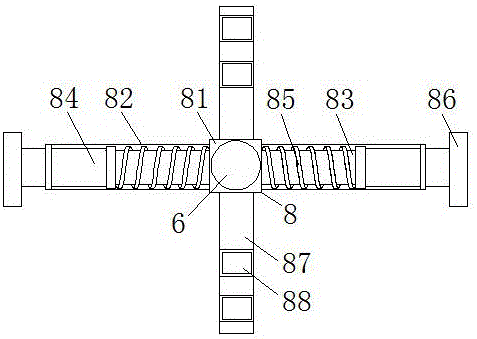
[0017] see figure 1 , a cleaning device for a mixer, comprising a housing 1, a base 2 is fixedly installed at the bottom of the housing 1, and a wheel 3 is movable on the bottom of the base 2, and the housing 1 is driven to move by the wheels 3, which improves the practicality of the mixer The middle part of the bottom end of the inner cavity of the housing 1 is fixedly installed with a bearing 4, which improves the stability of the rotation of the rotating sh...


PUM


Abstract

The invention discloses a clearing device of a stirring machine. The clearing device comprises a housing; a base is fixedly mounted at the bottom end of the housing; wheels are movably arranged at the bottom end of the base in a sleeving mode; a bearing is fixedly mounted in the middle of the bottom end of the inner cavity of the housing; a discharge valve, which is positioned on the side surface of the bearing, is fixedly mounted at the bottom end of the housing; the shaft center of the bearing is in movable sleeve connection with the bottom end of the rotary shaft; stirring paddles, which are positioned above the bearing, are fixedly arranged at the bottom end of the rotary shaft in the sleeving mode; a stirring device which is positioned above the stirring paddles is arranged on the rotary shaft in the sleeving mode; and the top end of the rotary shaft penetrates through the top end of the housing, extends to an inner cavity of a machine case, and is in movable sleeve connection with the top end of the inner cavity of the machine case. According to the clearing device disclosed by the invention, the stirring paddles are arranged for uniformly stirring a cement material, so that cement is uniformly distributed at the bottom end of the housing while stirred, cement adhered on the inner wall of the housing is scraped off by a scraping plate, and the cement is prevented from being solidified on the inner wall of the housing, and therefore, stirring efficiency is improved, and cost is saved.

Description

technical field [0001] The invention relates to the technical field of stirring equipment, in particular to a cleaning device for a stirring machine. Background technique [0002] A mixer is a machine with a bladed shaft that rotates in a cylinder or a tank to stir and mix various raw materials to make it a mixture or a suitable consistency. There are many kinds of mixers, such as forced mixers, single-shaft mixers, twin-shaft mixers, etc. Note: The mixer and automatic feeder must be cleaned inside, especially in winter, which can prolong the life. A mixer is a mixer, because the usual function of a mixer is to mix and mix various dry powder mortars, so it is commonly called a mixer. For example, CN 204673783 U discloses a horizontal cement mixer, which stirs the cement material through the rotation of the stirring shaft driven by the electric device, but the cement mixer cannot clean the inner wall of the housing when stirring, and it will make the The cement is solidifi...

Claims


Application Information

Patent Timeline
Patent Type & Authority Applications(China)
IPC IPC(8): B28C5/16
CPCB28C5/16B28C5/0806B28C5/0831
Inventor 杜旭升
Owner WUXI RISHENG CHEM CO LTD
Learn More