An automatic control multifunctional engraving machine

An automatic control and multi-functional technology, applied in decorative arts, processing models, painting tools, etc., can solve the problems of low degree of automation of the engraving machine, affecting the machining accuracy of the workpiece, time-consuming and laborious carving of the workpiece, etc., to achieve simple structure, improve quality, The effect of easy chip evacuation

Active Publication Date: 2020-01-07
扬州市生态科技新城润业中小企业服务中心有限公司
View PDF6 Cites 0 Cited by
  • Summary
  • Abstract
  • Description
  • Claims
  • Application Information

AI Technical Summary

Problems solved by technology

[0002] Nowadays, handicraft engraving is generally carried out by hand, which is time-consuming, labor-intensive and time-consuming, which is not conducive to industrial production. The existing engraving machine can intelligently engrave a workpiece with a single shape, and its function is relatively single. A few engraving machines with wide application range are automated Low, different processing procedures require replacement of props, and the tool change is usually completed by the operator through tool setting. Processing and engraving workpieces is time-consuming and laborious, and even affects the processing accuracy of the workpiece, reducing the productivity of the factory. After the processing is completed, the processing is full. Dust and sawdust, the environment is harsh, and it is very difficult to clean up; therefore, it is very necessary to provide an automatic control multifunctional engraving machine with simple structure, easy operation, high work efficiency, high precision, convenient and fast chip removal

Method used


Image

  • An automatic control multifunctional engraving machine
  • An automatic control multifunctional engraving machine

Examples


Embodiment 1

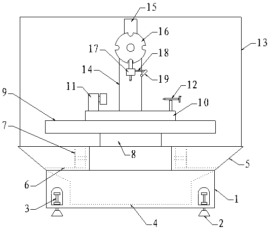
[0018] Such as figure 1 and figure 2 As shown, an automatic control multi-function engraving machine, it includes a base 1, the lower end of the base 1 is provided with a support bolt 3, the bottom of the base 1 is provided with an anchor 2, and the support bolt 3 Connected with the foundation 2, the inside of the machine base 1 is provided with a water tank 4, the upper side of the machine base 1 is provided with a dust collection box 5, and the upper side of the described dust collection box 5 is provided with a protective plate 13. A filter screen 6 is provided inside the dust collection box 5, an electric chip removal plate 7 is provided inside the dust collection box 5, an X-axis arm 8 is provided on the upper side of the machine base 1, and the X-axis arm 8, a Y-axis arm 9 is arranged on the upper side, and a working platform 10 is arranged on the upper side of the Y-axis arm 9. An electric dividing head 11 and a thimble 12 are arranged on the upper side of the working...

Embodiment 2

[0021] Such as figure 1 and figure 2 As shown, an automatic control multi-function engraving machine, it includes a base 1, the lower end of the base 1 is provided with a support bolt 3, the bottom of the base 1 is provided with an anchor 2, and the support bolt 3 Connected with the foundation 2, the inside of the machine base 1 is provided with a water tank 4, the upper side of the machine base 1 is provided with a dust collection box 5, and the upper side of the described dust collection box 5 is provided with a protective plate 13. A filter screen 6 is provided inside the dust collection box 5, an electric chip removal plate 7 is provided inside the dust collection box 5, an X-axis arm 8 is provided on the upper side of the machine base 1, and the X-axis arm 8, a Y-axis arm 9 is arranged on the upper side, and a working platform 10 is arranged on the upper side of the Y-axis arm 9. An electric dividing head 11 and a thimble 12 are arranged on the upper side of the working...


PUM


Abstract

The invention relates to an automatic-control multi-functional carving machine. The automatic-control multi-functional carving machine comprises a machine base; supporting bolts are arranged at the lower end of the machine base; foot margins are arranged at the lower portion of the machine base and are connected with the supporting bolts; a water tank is arranged inside the machine base; a scrap collecting box is arranged at the upper side of the machine base; a protective plate is arranged at the upper side of the scrap collecting box; a filter screen is arranged inside the scrap collecting box; an electric scrap discharging plate is arranged inside the scrap collecting box; an X-axis arm is also arranged at the upper side of a working platform; a Y-axis arm is arranged at the upper side of the X-axis arm; the working platform is arranged at the upper side of the Y-axis arm; an electric dividing head and a thimble are arranged at the upper side of the working platform; an upright post is also arranged at the upper side of the machine base; a Z-axis arm is arranged at the upper side of the upright post; a cutter replacing disc is arranged at the front side of the lower part of the Z-axis arm; the lower end of the Z-axis arm is connected with a main shaft; a bracket is arranged at the side surface of the main shaft; a spraying pipe is arranged at the tail end of the bracket and is connected with a power pump. The automatic-control multi-functional carving machine disclosed by the invention has the advantages of being simple in structure, simple and convenient to operate, high in work efficiency, high in precision and capable of conveniently and quickly discharging scraps.

Description

technical field [0001] The invention belongs to the technical field of engraving processing equipment, and in particular relates to an automatic control multifunctional engraving machine. Background technique [0002] Nowadays, handicraft engraving is generally carried out by hand, which is time-consuming, labor-intensive and time-consuming, which is not conducive to industrial production. The existing engraving machine can intelligently engrave a workpiece with a single shape, and its function is relatively single. A few engraving machines with wide application range are automated Low, different processing procedures require replacement of props, and the tool change is usually completed by the operator through tool setting. Processing and engraving workpieces is time-consuming and laborious, and even affects the processing accuracy of the workpiece, reducing the productivity of the factory. After the processing is completed, the processing is full. Dust and sawdust, the env...

Claims


Application Information

Patent Timeline
Patent Type & Authority Patents(China)
IPC IPC(8): B44B1/00B44B1/06
CPCB44B1/00B44B1/06B44B2700/04B44B2700/12
Inventor 孔艳阳张宏山朱业革
Owner 扬州市生态科技新城润业中小企业服务中心有限公司
Why Eureka
Try Eureka