Walking steering mechanism and seepage-preventing ditch cast-in-situ forming machine

A technology of steering mechanism and molding machine, which is applied in water conservancy projects, artificial waterways, buildings, etc., and can solve problems such as inability to realize steering work, inability to fully utilize the working potential of anti-seepage canal cast-in-place molding equipment, complex steering mechanisms, etc.

Active Publication Date: 2017-02-08
YANCHENG XINSUYUAN MACHINERY MFG
View PDF5 Cites 0 Cited by
  • Summary
  • Abstract
  • Description
  • Claims
  • Application Information

AI Technical Summary

Problems solved by technology

The anti-seepage canal is generally poured by the anti-seepage canal cast-in-place forming machine. During the pouring process, the anti-seepage canal cast-in-place forming machine uses the rollers to contact the ground to realize walking, and can only walk in a straight line, and cannot turn to work. The work is very limited Large, unable to fully utilize the full working potential of the anti-seepage canal cast-in-place forming equipment
In order to realize the steering of the rollers of the anti-seepage canal cast-in-place forming machine, a more complicated steering mechanism needs to be added

Method used


Image

  • Walking steering mechanism and seepage-preventing ditch cast-in-situ forming machine
  • Walking steering mechanism and seepage-preventing ditch cast-in-situ forming machine
  • Walking steering mechanism and seepage-preventing ditch cast-in-situ forming machine

Examples


Embodiment 1

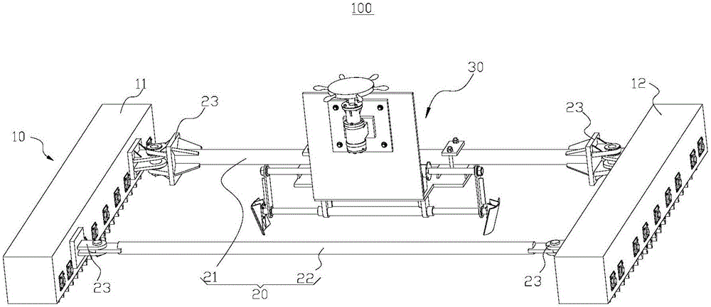
[0035] like figure 1 As shown, this embodiment provides a walking steering mechanism 100 , including a walking assembly 10 , a connecting assembly 20 and a driving device 30 .

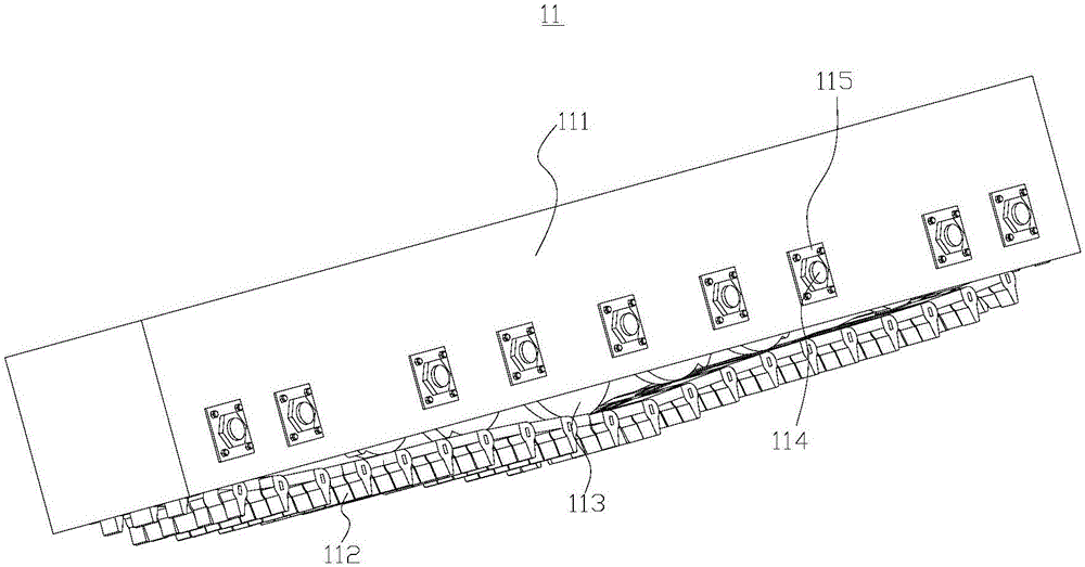
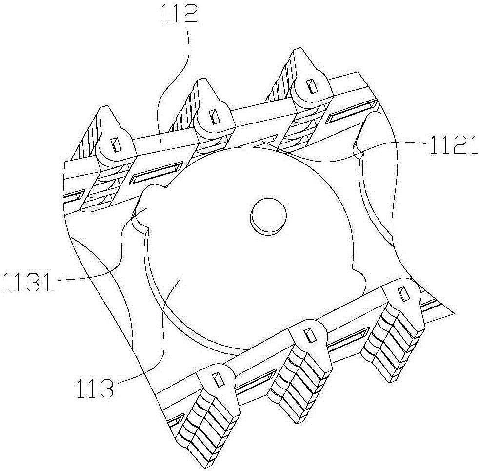
[0036] Specifically, the walking assembly 10 includes a first walking part 11 and a second walking part 12 . like figure 2 As shown, the first running part 11 includes a frame body 111 , caterpillar belts 112 and several runners 113 . The frame body 111 is a cuboid structure, which forms a receiving cavity with an open bottom, and a plurality of bearing seats 115 are provided on both side walls of the frame body 111 in the width direction. The runners 113 are located in the receiving cavity, and the runners 113 are all connected to the frame body 111 through the rotating shaft 114 , and the two ends of the rotating shaft 114 are connected to the bearing seats 115 on the frame body 111 through bearings. The track 112 is partially located in the accommodation cavity, and the frame body 111 can play a...

Embodiment 2

[0056] like Image 6 As shown, the difference between this embodiment and Embodiment 1 is that the first rib 3312 in the first toggle member 331 and the first movable body 3222 in the two-way moving rod 322 are rotationally connected by a pin shaft, and the second toggle The second rib 3322 in the member 332 is rotatably connected with the second movable body 3223 in the two-way moving rod 322 through a pin shaft. A first hydraulic cylinder 34 is provided between the first scraper 3311 and the first movable body 3222. One end of the first hydraulic cylinder 34 is hinged to the first scraper 3311, and the other end of the first hydraulic cylinder 34 is hinged to the first movable body 3222. . A second hydraulic cylinder 35 is provided between the second scraper 3321 and the second movable body 3223, one end of the second hydraulic cylinder 35 is hinged to the second scraper 3321, and the other end of the second hydraulic cylinder 35 is hinged to the second movable body 3223 ....

Embodiment 3

[0060] like Figure 7 As shown, this embodiment provides an anti-seepage canal cast-in-place forming machine 200, which includes a forming machine body 210 and the travel steering mechanism 100 in the above-mentioned embodiments.

[0061] Wherein, the molding machine body 210 can complete the casting work on the channel, so that the channel will not leak. The specific structure of the molding machine body 210 is the same as that of the prior art. Of course, the molding machine body 210 should be equipped with an oil supply system for supplying oil to each hydraulic component.

[0062] The molding machine body 210 is placed on the first running part 11 and the second running part 12, and the first running part 11 and the second running part 12 are both rotatably connected with the molding machine body 210, that is, the molding machine body 210 can move relative to the first running part 11 and the second running part 12 rotate in the horizontal plane.

[0063] The anti-seepag...


PUM


Abstract

The invention provides a walking steering mechanism and a seepage-preventing ditch cast-in-situ forming machine and belongs to the field of agricultural machinery. The walking steering mechanism comprises a walking assembly, a connection assembly and a driving device. The walking assembly comprises a first walking component and a second walking component which are parallel with each other. The connection assembly comprises a first connection rod and a second connection rod. The two ends of the first connection rod are connected with the first walking component and the second walking component in a rotary manner correspondingly. The two ends of the second connection rod are connected with the first walking component and the second walking component in a rotary manner correspondingly. The driving device is fixedly connected with the first connection rod. Under the action of the driving device, when the first connection rod is made to rotate relative to the first walking component and the second walking component, steering is achieved. The walking steering mechanism is simple in structure and simple and convenient in steering form. The seepage-preventing ditch cast-in-situ forming machine provided with the walking steering mechanism has a certain steering function; work limitation of the seepage-preventing ditch cast-in-situ forming machine is lowered; and the seepage-preventing ditch cast-in-situ forming machine can perform higher work potential.

Description

technical field [0001] The invention relates to the field of agricultural machinery, in particular to a walking steering mechanism and an anti-seepage canal cast-in-place forming machine. Background technique [0002] At present, the whole society vigorously promotes water-saving irrigation measures, and seepage-proof channels are an important part of water-saving irrigation. The anti-seepage canal is generally poured by the anti-seepage canal cast-in-place forming machine. During the pouring process, the anti-seepage canal cast-in-place forming machine uses the rollers to contact the ground to realize walking, and can only walk in a straight line, and cannot turn to work. The work is very limited Large, unable to give full play to the full working potential of the anti-seepage canal cast-in-place forming equipment. To realize the steering of the rollers of the anti-seepage canal cast-in-place forming machine, a more complicated steering mechanism needs to be added. Conte...

Claims


Application Information

Patent Timeline
IPC IPC(8): E02B5/02
CPCE02B5/02
Inventor 孙素元赵振秀汤沛孙建东夏基胜
Owner YANCHENG XINSUYUAN MACHINERY MFG
Why Eureka
Try Eureka