Point light source welding seam scanning detection method

A detection method and technology of point light source, applied in measurement devices, optical devices, instruments, etc., can solve the problems of large detection equipment, difficult to visualize imaging, missed detection, etc., achieve accurate imaging signals, save labor costs, and have a wide range of applications Effect

Inactive Publication Date: 2017-02-08
GUANGDONG UNIV OF TECH
View PDF7 Cites 16 Cited by
  • Summary
  • Abstract
  • Description
  • Claims
  • Application Information

AI Technical Summary

Problems solved by technology

[0003] The above detection methods have certain limitations. Among them, ultrasonic detection has high requirements for operators, and it is difficult to distinguish different types of welding defects. It requires couplant, and it is difficult to visualize imaging; the cost of radiographic detection is high, and the detection equipment is relatively expensive. Large, the radiation radiation produced is extremely harmful to the human body; the width and height of the butt weld, the fillet size of the fillet weld, etc. are measured by the measuring instrument weld size measuring ruler, and its scientificity and accuracy are subject to inspection personnel. Influenced by subjective factors; the application of magnetic particle inspection and penetrant inspection methods can only detect qualitatively the opening defects on the weld surface, and it is difficult to quantitatively evaluate; it is difficult to meet the industrial requirements for rapid and accurate detection by visual inspection methods. Missed inspections may be caused by careless observation of the surveyors

Method used


Image

  • Point light source welding seam scanning detection method
  • Point light source welding seam scanning detection method
  • Point light source welding seam scanning detection method

Examples


Embodiment Construction

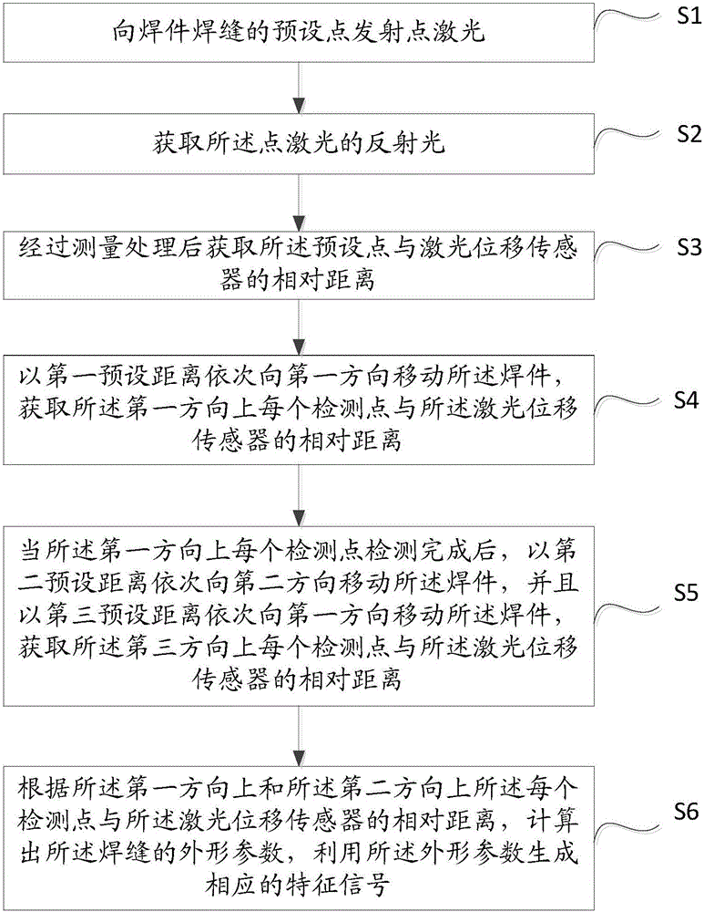
[0028] The core of the present invention is to provide a detection method of point light source scanning welding seam, which effectively realizes the automatic detection of welding seam forming condition.

[0029] The following will clearly and completely describe the technical solutions in the embodiments of the present invention with reference to the accompanying drawings in the embodiments of the present invention. Obviously, the described embodiments are only some, not all, embodiments of the present invention. Based on the embodiments of the present invention, all other embodiments obtained by persons of ordinary skill in the art without making creative efforts belong to the protection scope of the present invention.

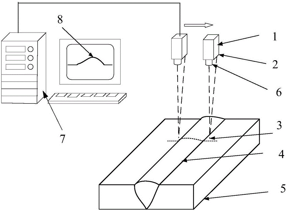
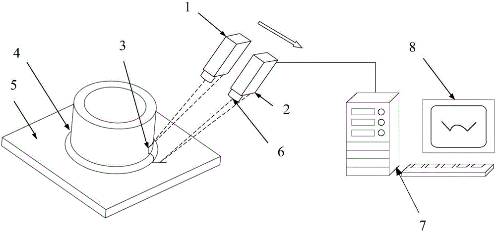
[0030] Please refer to Figure 1 to Figure 4 , figure 1 It is a flow chart of the detection method of point light source scanning welding seam provided by a specific embodiment of the present invention; figure 2 for adoption figure 1 Schematic diagram o...


PUM


Abstract

The invention discloses point light source welding seam scanning detection method, which comprises the steps of emitting point laser to a preset point on a welding seam of a weldment; acquiring reflected light of the point laser; acquiring the relative distance between the preset point and a laser displacement sensor after measurement processing; moving the weldment towards a first direction in sequence by a first preset distance, and acquiring the relative distance between each detection point in the first direction and the laser displacement sensor; moving the weldment towards a second direction in sequence by a second preset distance after each detection point in the first direction is detected, moving the weldment towards the first direction in sequence by a third preset distance, and acquiring the relative distance between each detection point in the third direction and the laser displacement sensor; and calculating shape parameters of the welding seam according to the relative distance between each detection point in the first direction and the laser displacement sensor and the relative distance between each detection point in the second direction and the laser displacement sensor, and generating corresponding characteristic signals by using the shape parameters. The point light source welding seam scanning detection method effectively realizes automatic detection for forming conditions of a welding seam.

Description

technical field [0001] The invention relates to the technical field of weld seam detection, in particular to a detection method for point light source scanning weld seam. Background technique [0002] The quality inspection during the welding process is very important. At present, the quality inspection of the weld mainly includes the appearance of the weld and the surface defect inspection, the internal defect inspection of the weld, and the various performance inspections of the weld. The detection of internal defects of the weld is mainly realized by non-destructive testing methods such as ray and ultrasonic flaw detection. Various performance tests of welds include testing of mechanical properties and corrosion properties. The weld appearance and surface defect inspection are the most widely used, and basically all industrial welds must be inspected for appearance and surface defects. In addition to internal testing requirements, strict weld appearance and surface defe...

Claims


Application Information

Patent Timeline
Patent Type & Authority Applications(China)
IPC IPC(8): G01B11/00G01B11/06G01B11/24
CPCG01B11/00G01B11/06G01B11/24
Inventor 高向东蓝重洲
Owner GUANGDONG UNIV OF TECH
Why Eureka
Try Eureka