Measuring device and method of laser vibration measuring instrument step response

A technology of laser vibrometer and step response, which is applied in the direction of measuring device, ultrasonic/sonic wave/infrasonic wave, instrument, etc. The stability is not as good as the vibrometer and other problems, so as to avoid the effect of high-quality step signal, wide frequency range and large amplitude range

Inactive Publication Date: 2017-02-08
BEIJING CHANGCHENG INST OF METROLOGY & MEASUREMENT AVIATION IND CORP OF CHINA
View PDF10 Cites 8 Cited by
  • Summary
  • Abstract
  • Description
  • Claims
  • Application Information

AI Technical Summary

Problems solved by technology

[0004] The purpose of the present invention is to solve the main problem that the technical parameters limited by the mechanical movement of the vibrating table cannot completely cover the range of the vibrometer and the stability is not as good as that of the vibrometer in the calibration of the laser vibrometer, and the standard laser vibrometer In order to solve the problems that cannot be completely solved by instrumentation traceability, a measurement device and measurement method for the step response of laser vibrometers is proposed

Method used


Image

  • Measuring device and method of laser vibration measuring instrument step response
  • Measuring device and method of laser vibration measuring instrument step response
  • Measuring device and method of laser vibration measuring instrument step response

Examples


Embodiment Construction

[0023] The present invention will be further described below in conjunction with the accompanying drawings and embodiments.

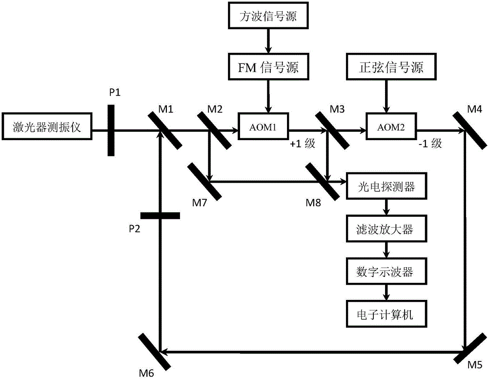
[0024] Such as figure 1 As shown, a laser vibrometer step response measurement device includes a laser vibrometer, a first polarizer (P1), a second polarizer (P2), a polarizing mirror (M1), a first semi-transparent and half-reflective mirror (M2), first acousto-optic modulator (AOM1), second acousto-optic modulator (AOM2), FM signal source, square wave signal source, sine signal source, second half mirror (M3), second One mirror (M4), second mirror (M5), third mirror (M6), fourth mirror (M7), third half mirror (M8), photodetector, filter amplifier, digital Oscilloscopes and computers.

[0025] The specific measurement method is:

[0026] The frequency-stabilized laser light emitted by the laser vibrometer passes through the first polarizer (P1), the polarizing mirror (M1), and is transmitted to the first half-mirror (M2). The optical modulator (AOM1...


PUM


Abstract

The present invention relates to a measuring device and method of laser vibration measuring instrument step response and belongs to the photoelectric measurement technical field. The measuring device of the present invention comprises a measured laser vibration measuring instrument, a polarizer P1, a polarizer P2, a polarizing reflector M1, a semi-transmitting and semi-reflection mirror M2, an acousto-optic modulator AOM1, an acousto-optic modulator AOM2, an FM signal source, a square wave signal source, a sinusoidal signal source, a semi-transmitting and semi-reflection mirror M3, reflectors M4, M5, M6 and M7, a semi-transmitting and semi-reflection mirror M8, a photoelectric detector and the like. Optical frequency modulation signals are down-converted into a radio frequency range through beat-frequency processing; a signal waveform sequence is obtained by means of high-speed data acquisition and quantization technologies; instantaneous frequency accurate demodulation of laser frequency modulation signal waveforms is realized through a digitization mode, so that standard motion velocity waveforms and motion acceleration waveforms can be obtained; and problems in accurate measurement and value traceability of the step response of the laser vibration measuring instrument can be solved.

Description

technical field [0001] The invention relates to a measuring device and method for a step response of a laser vibrometer, belonging to the technical field of photoelectric measurement. Background technique [0002] The laser vibrometer is a general-purpose, basic vibration and shock measuring instrument with high precision, non-contact, and no additional interference and influence on the measured object. Its measurement and calibration has always been a difficult problem in the industry, mainly because Its excitation is the movement value (displacement, velocity, acceleration), and the measurement principle used is carried out through the laser Doppler effect. It needs to perceive the physical movement through the change of optical frequency, and the output is given in the form of electrical signal data. Various aspects such as mechanical movement, optical frequency control, and electronic measurement. [0003] Usually its metrological calibration is excited by the "standard...

Claims


Application Information

Patent Timeline
Patent Type & Authority Applications(China)
IPC IPC(8): G01H9/00
CPCG01H9/00
Inventor 梁志国朱振宇
Owner BEIJING CHANGCHENG INST OF METROLOGY & MEASUREMENT AVIATION IND CORP OF CHINA
Why Eureka
Try Eureka