Check patentability & draft patents in minutes with Patsnap Eureka AI!

Voltage isolated sampling circuit

A sampling circuit and voltage isolation technology, applied in the power supply field, can solve problems such as complex structure, poor anti-interference ability, and limited application range, and achieve the effect of simple circuit structure, strong anti-interference ability, and wide application range

Active Publication Date: 2019-05-07
SUZHOU MAILI ELECTRICAL APPLIANCE
View PDF6 Cites 0 Cited by
  • Summary
  • Abstract
  • Description
  • Claims
  • Application Information

AI Technical Summary

Problems solved by technology

[0002] DC voltage isolation sampling is a commonly used voltage sampling circuit. There are many DC voltage sampling circuits with different structures in the prior art, mainly including the following methods: (1) The linear isolation optocoupler method is adopted. The DC voltage sampling circuit of this structure The voltage isolation sampling circuit meets the general needs. The DC voltage isolation sampling circuit generally uses HCNR200 / 201 series optocouplers, which have high cost and poor anti-interference ability
(2) The DC Hall method is adopted. The DC voltage isolation sampling circuit with this structure has complex circuit structure, limited application range and high cost.
(3) Using a voltage-frequency conversion circuit, the traditional voltage-frequency conversion circuit uses a special analog-to-digital conversion function control chip, but the structure of the voltage-frequency conversion circuit based on this type of chip is generally more complicated and the cost is higher

Method used


Image

  • Voltage isolated sampling circuit

Examples


Embodiment Construction

[0014] The technical solutions in the embodiments of the present invention will be clearly and completely described below in conjunction with the accompanying drawings in the embodiments of the present invention. Obviously, the described embodiments are only a part of the embodiments of the present invention, rather than all the embodiments. Based on the embodiments of the present invention, all other embodiments obtained by those of ordinary skill in the art without creative work shall fall within the protection scope of the present invention.

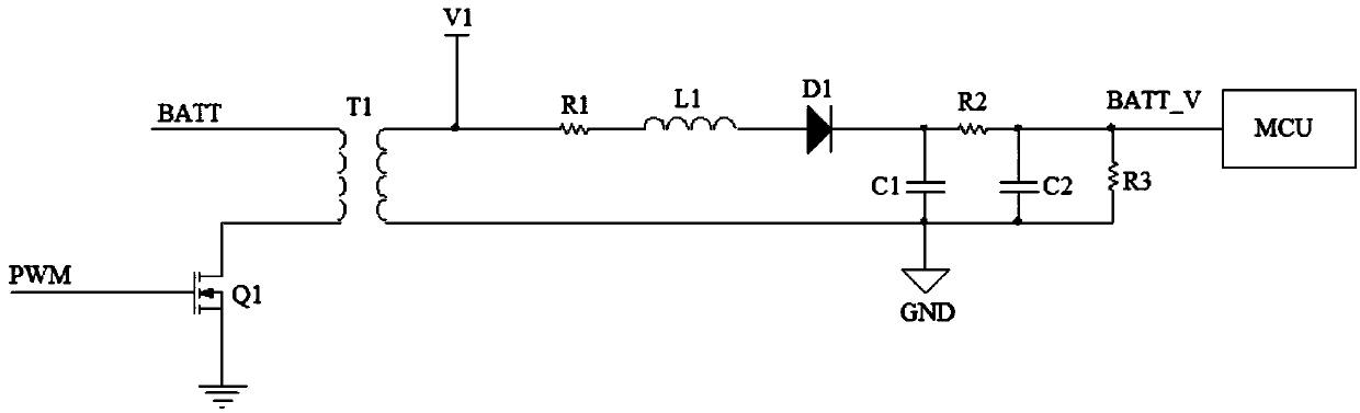
[0015] In the embodiment of the voltage isolation sampling circuit of the present invention, the structure diagram of the voltage isolation sampling circuit is as figure 1 Shown. figure 1 Wherein, the voltage isolation sampling circuit includes a first MOS transistor Q1, an isolation transformer T1, a first resistor R1, a first inductor L1, a first diode D1, a first capacitor C1, a second resistor R2, a third resistor R3 and MCU, the fi...


PUM


Abstract

The invention discloses a voltage isolated sampling circuit. The circuit comprises a first MOS tube, an isolation transformer, a first resistor, a first inductor, a first diode, a first capacitor, a second resistor, a third resistor and an MCU; the grid of the first MOS tube inputs a PWM control signal; one end of a primary coil of the isolation transformer is connected to an access voltage, the other end of the primary coil of the isolation transformer is connected with the drain of the first MOS tube, and one end of a secondary coil of the isolation transformer is connected to a first voltage, and also connected with one end of the first diode via the first resistor and the first inductor; the other end of the first diode is connected with one end of the first capacitor and one end of the second resistor; the other end of the second resistor is connected with one end of the third resistor, and outputs a isolated sampling voltage to the MCU; and the other end of the first capacitor and the other end of the third resistor are grounded. The voltage isolated sampling circuit is simple in circuit structure, lower in cost, higher in anti-interference capability and wider in application range.

Description

Technical field [0001] The invention relates to the field of power supplies, in particular to a voltage isolation sampling circuit. Background technique [0002] DC voltage isolation sampling is a commonly used voltage sampling circuit. There are many types of DC voltage sampling circuits with different structures in the prior art, mainly including the following methods: (1) Linear isolation optocoupler method is adopted. The voltage isolation sampling circuit meets the general needs. The DC voltage isolation sampling circuit generally uses the HCNR200 / 201 series optocoupler, which has high cost and poor anti-interference ability. (2) The DC Hall method is adopted. The DC voltage isolation sampling circuit of this structure has a complicated circuit structure, limited use range and high cost. (3) Voltage-frequency conversion circuits are used. Traditional voltage-frequency conversion circuits all use special analog-to-digital conversion function control chips, but the structure ...

Claims


Application Information

Patent Timeline
Patent Type & Authority Patents(China)
IPC IPC(8): G01R19/00
CPCG01R19/0084
Inventor 朱海东
Owner SUZHOU MAILI ELECTRICAL APPLIANCE
Features
  • R&D
  • Intellectual Property
  • Life Sciences
  • Materials
  • Tech Scout
  • Unparalleled Data Quality
  • Higher Quality Content
  • 60% Fewer Hallucinations
Learn More