
Chemical stirring tank capable of achieving premixing and being conveniently cleaned

A mixing tank and pre-mixing technology, which is applied in the field of chemical mixing tanks, can solve the problems of reducing production efficiency, increasing labor intensity of workers, and insufficient mixing of materials, so as to speed up work efficiency, improve cleaning efficiency and cleaning quality, and improve work efficiency Effect

Inactive Publication Date: 2017-02-15
李伟科
View PDF7 Cites 8 Cited by
  • Summary
  • Abstract
  • Description
  • Claims
  • Application Information

AI Technical Summary

Problems solved by technology

[0002] At present, with the development of science and technology, mixing tanks are widely used in the food production industry in pharmaceutical and chemical industries. Usually, mixing tanks are used to accelerate the reaction of materials in the kettle and make the materials homogeneous. In order to achieve the purpose of mixing, in some chemical raw materials It is often necessary to add other raw materials in the process to fully mix the chemical raw materials into other raw materials. The typical structure of the existing stirring tank is that a stirring device is fixed outside the stirring tank, and the stirring device is used to drive the agitator extending into the reaction tank. The material is stirred, but the existing mixing tank often has the situation of material accumulation, the mixing of the material is not sufficient, and the existing mixing tank does not have the function of automatic cleaning, it needs to be cleaned manually, which increases the labor intensity of the workers. reduced productivity

Method used


Image

  • Chemical stirring tank capable of achieving premixing and being conveniently cleaned
  • Chemical stirring tank capable of achieving premixing and being conveniently cleaned
  • Chemical stirring tank capable of achieving premixing and being conveniently cleaned

Examples


Embodiment Construction

[0017] The technical solution of this patent will be further described in detail below in conjunction with specific embodiments.

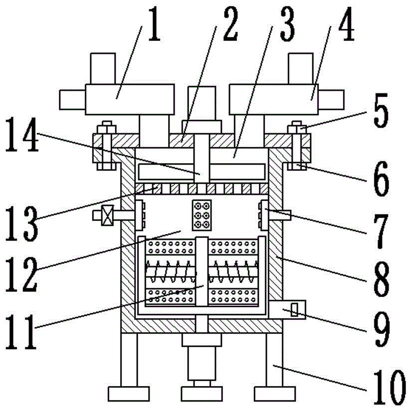
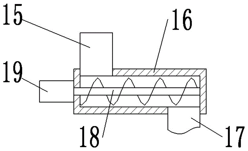
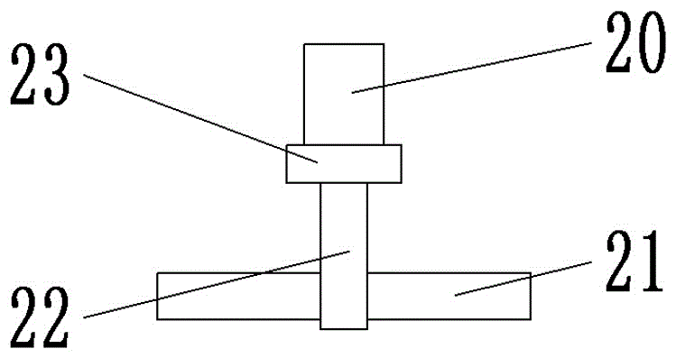
[0018] see Figure 1-5 , a chemical mixing tank that is easy to clean and can be pre-mixed, including a tank body 8 and an upper cover 2; the tank body 8 is set as a hollow cylinder, and the interior is divided into a pre-mixing chamber 3 and a stirring chamber 12 by a partition 13 ; The partition 13 is evenly distributed with some through holes; the top opening of the tank body 8 is provided with a loam cake 2; the loam cake 2 is provided with a feed device; the feed device is divided into a first feed device 1 and the second feeding device 4; the first feeding device 1 and the second feeding device 4 are arranged on the left and right sides of the upper cover 2, and the first feeding device 1 and the second feeding device 4 are all fed by Tube 16 and feeding tube 15 are composed; the feeding tube 16 is arranged horizontally, both ends are closed...


PUM


Abstract

The invention provides a chemical stirring tank capable of achieving premixing and being conveniently cleaned. The chemical stirring tank comprises a tank body and an upper cover; the interior of the tank body is partitioned into a premixing cavity and a stirring cavity through a partition plate; the upper cover is provided with feeding devices which comprise the first feeding device and the second feeding device; a premixing device is arranged in the premixing cavity and composed of a mixing motor, a mixing rotation shaft and mixing sheets; a cleaning device is arranged on the top of the stirring cavity and composed of a water pipe, spray heads and a pressurizing pump; a stirring device is arranged at the bottom of the stirring cavity and composed of a stirring motor, a stirring shaft, stirring sheets and a scraper plate. According to the chemical stirring tank, materials are added into the premixing cavity through the first feeding device and the second feeding device at uniform speed, and therefore the adding amount of the materials can be conveniently controlled; the materials are premixed through the premixing device; the materials are fully stirred through the stirring device.

Description

technical field [0001] The invention relates to a chemical mixing equipment, in particular to a chemical mixing tank which is easy to clean and can be mixed in advance. Background technique [0002] At present, with the development of science and technology, mixing tanks are widely used in the food production industry in pharmaceutical and chemical industries. Usually, mixing tanks are used to accelerate the reaction of materials in the kettle and make the materials homogeneous. In order to achieve the purpose of mixing, in some chemical raw materials It is often necessary to add other raw materials in the process to fully mix the chemical raw materials into other raw materials. The typical structure of the existing stirring tank is that a stirring device is fixed outside the stirring tank, and the stirring device is used to drive the agitator extending into the reaction tank. The material is stirred, but the existing mixing tank often has the situation of material accumulat...

Claims


Application Information

Patent Timeline
Patent Type & Authority Applications(China)
IPC IPC(8): B01F7/18B01F7/24B01F15/00B01F15/02
CPCB01F27/074B01F27/091B01F27/112B01F27/1143B01F27/1921B01F27/808B01F27/851B01F27/9214B01F27/90B01F35/1453B01F35/123B01F35/52B01F35/71775
Inventor 李伟科
Owner 李伟科
Learn More