Detection device for ecological environment pollution
A detection device and ecological technology, applied in the direction of soil material testing, material inspection products, test tube holders/clamps, etc., can solve the problems of inconvenience, ecological environment pollution, inconvenient placement of test tubes on test tube storage supports, etc.
- Summary
- Abstract
- Description
- Claims
- Application Information
AI Technical Summary
Problems solved by technology
Method used
Image
Examples
Embodiment 1
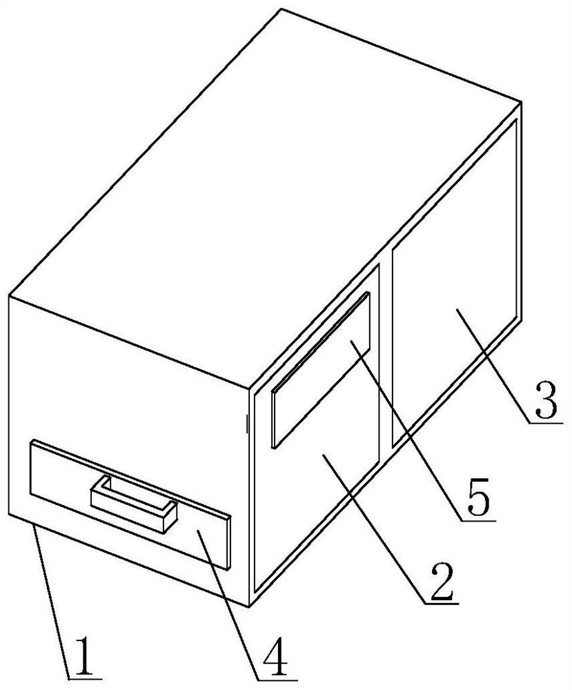
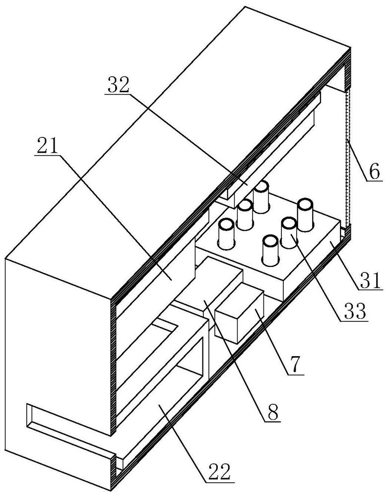
[0030] Such as Figure 1-Figure 7 As shown, the present invention provides a detection device for ecological environment pollution, comprising a detection box 1, the detection box 1 includes a first detection chamber 2 and a second detection chamber 3, and the left side of the detection box 1 is slidingly connected There is a placement plate 4 , and a display screen 5 is arranged on the outer wall of the first detection chamber 2 .
[0031] In this embodiment, it is convenient to place the soil to be detected on the placement plate 4 and push it into the inside of the first detection chamber 2, while the first detection chamber 2 and the second detection chamber 3 are mutually The independent confined space avoids the influence of molecular propagation on the detection results, and the setting of the display screen 5 is convenient for observing the detection results. The display screen 5 is equipped with a controller inside, and can control the switch of the air pump 8, which ...
Embodiment 2
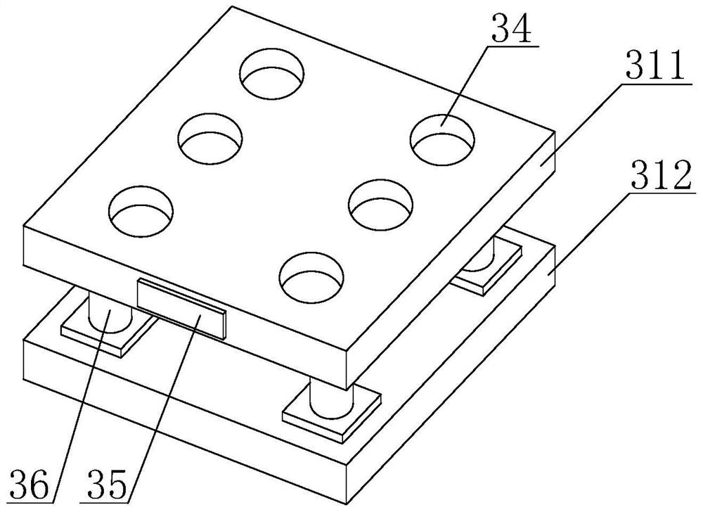
[0034] Such as Figure 2-5Shown, on the basis of embodiment 1, the present invention provides a kind of technical scheme: test tube storage support 31 comprises first support 311 and second support 312, and the top of first support 311 is provided with test tube hole 34, and test tube hole 34 One side is provided with elastic member 342, and one end of elastic member 342 is fixedly connected with arc-shaped clamp block 341, and arc-shaped clamp block 341 is elastically connected with test tube hole 34 by elastic member 342 provided, and the surface of arc-shaped clamp block 341 and test tube 33 and when the test tube 33 is put into the test tube hole 34 through the arc-shaped clamp block 341, the arc-shaped clamp block 341 will move to both sides under the thrust from the test tube 33, and compress the elastic member 342 in the process of moving, thereby Trigger the elastic potential energy of the elastic member 342, and there is a reaction force to the arc clamp 341, so that ...
Embodiment 3
[0036] Such as Figure 6-7 As shown, on the basis of Embodiment 1 and Embodiment 2, the present invention provides a technical solution: preferably, the inner wall of the first bracket 311 is provided with a connecting plate 313 and a pop-up block 317, and the outer wall of the connecting plate 313 is connected to the second The inner wall of a bracket 311 is slidingly connected, and the connecting plate 313 can slide inside the first bracket 311, and the pull block provided on the surface of the connecting plate 313 can drive the movement of the connecting plate 313 through the movement of the pulling block, so that the test tube 33 can be moved upwards. Move a certain distance, reduce the clamping force of the arc-shaped clamp block 341 to the test tube 33, facilitate the test tube to be taken out, the top of the connecting plate 313 overlaps with the bottom of the test tube hole 34, and the bottom of the pop-up block 317 and the first support The bottom of the inner wall of...
PUM
 Abstract
Description
Claims
Application Information
 - R&D
- Intellectual Property
- Life Sciences
- Materials
- Tech Scout
- Unparalleled Data Quality
- Higher Quality Content
- 60% Fewer Hallucinations
Browse by: Latest US Patents, China's latest patents, Technical Efficacy Thesaurus, Application Domain, Technology Topic, Popular Technical Reports.
© 2025 PatSnap. All rights reserved.Legal|Privacy policy|Modern Slavery Act Transparency Statement|Sitemap|About US| Contact US: help@patsnap.com


