
Counterbore countersink drill and machining process thereof

A countersinking and countersinking technology, which is applied in the direction of drilling/drilling equipment, metal processing equipment, boring machine/drilling machine parts, etc., can solve the problem of increasing the clamping force of drill bits and taps, coaxiality errors, hole drilling and countersinking Problems such as the complexity of the drill replacement process, to achieve the effect of increased clamping force, stable clamping state, and clear processing process

Inactive Publication Date: 2017-02-15
YANGZHOU SHILI HARDWARE TOOL IND & TRADE CO LTD
View PDF6 Cites 1 Cited by
  • Summary
  • Abstract
  • Description
  • Claims
  • Application Information

AI Technical Summary

Problems solved by technology

[0004] The present invention aims at the disadvantages of the traditional hole drill and countersink being unstable in the holder, the replacement process of the hole drill and the countersink is complicated, and the coaxiality error is easy to occur during the replacement, and a countersinking countersink and countersinking are proposed. The processing technology of countersinking can greatly increase the clamping force of the drill bit and the tap in the fixture. After the drilling is completed, the countersinking process can be performed quickly, which can not only improve the accuracy of drilling and countersinking, but also improve the processing efficiency. effectively improve

Method used


Image

  • Counterbore countersink drill and machining process thereof
  • Counterbore countersink drill and machining process thereof
  • Counterbore countersink drill and machining process thereof

Examples


Embodiment Construction

[0041] The present invention will be further described below in conjunction with accompanying drawing:

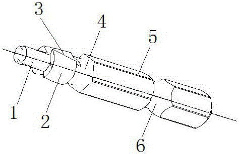
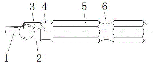
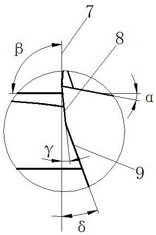
[0042] Such as Figure 1-5 As shown, a countersinking countersinking drill is composed of a guide post 1, a countersinking cutting post 2 and a drill shank 5, a tool groove 4 is provided between the countersinking cutting post 2 and the drill shank 5, and the guide post 1 and the surface of the counterbore cutting column 2 are provided with a chip removal groove 3 connected with a thread lead angle α, and the chip removal groove 3 with a thread lead angle α starts from the head of the guide post 1 and ends at the tool groove In 4, the middle part of the drill shank 5 is provided with a quick connection groove 6, the head of the guide post 1 is provided with the opening angle of the guide post, and the end face of the head of the counterbore cutting post 2 is provided with a first cutting edge formed by a first cutting edge 8. plane and the second cutting plane formed by th...


PUM

PropertyMeasurementUnit
radiusaaaaaaaaaa
lengthaaaaaaaaaa

Abstract

The invention provides a counterbore countersink drill and a machining process thereof and belongs to the technical field of machining equipment. The counterbore countersink drill is composed of a guide column, a counterbore cutting column and a drill handle. A cutter relieving groove is formed between the counterbore cutting column and the drill handle. A coherent chip removing groove with a lead angle Alpha is formed in the surface of the guide column and the surface of the counterbore cutting column, starts at the head of the guide column and ends in the cutter relieving groove. The middle of the drill handle is provided with a rapid receiving groove. The head of the guide column is provided with a guide column opening angle. The end surface of the head of the counterbore cutting column is provided with a first cutting plane composed of a first cutting edge and a second cutting plane composed of a second cutting edge. The first cutting edge and the basal plane form a first relief angle Gamma. The second cutting edge and the basal plane form a second relief angle Delta. The outer circle surface of the guide column and the basal plane form a counterbore cutting column opening angle Beta. According to the counterbore countersink drill and the machining process thereof, the structure is reasonable; the machining process is clear in procedure; the positioning precision and the machining precision of the counterbore countersink drill are significantly improved compared with those of a traditional hole drill and a traditional countersink drill; and the machining efficiency of drilling and countersinking is improved.

Description

technical field [0001] The invention belongs to the technical field of machining equipment, and relates to a machining tool and a processing technology, in particular to a countersinking and countersinking processing technology. Background technique [0002] Drilling and countersinking are common processing methods in machining. Drilling is the process of machining holes on solid materials with a drill bit. During the drilling process, except for a part completed by lathes, boring machines, and milling machines, it is very large. Part of it is done by the fitter using a drill press and drilling tools (drill, reamer, reamer, etc.); while countersinking refers to processing cylindrical countersinks, tapered countersinks and bosses on the processed holes. Section, etc., the purpose of countersinking is to ensure the perpendicularity between the hole and the centerline of the hole, so that the position of the parts connected to the hole is correct and the connection is reliable....

Claims


Application Information

Patent Timeline
Patent Type & Authority Applications(China)
IPC IPC(8): B23B51/10B23P15/28
CPCB23B51/107B23B2251/04B23B2251/043B23B2251/408B23P15/28
Inventor 张琦
Owner YANGZHOU SHILI HARDWARE TOOL IND & TRADE CO LTD
Learn More