Automatic spin welding tool for circular seams of pipe fittings

A technology of automatic rotation and welding tooling, applied in welding equipment, auxiliary welding equipment, welding/cutting auxiliary equipment, etc., can solve the problems of affecting appearance quality, low work efficiency, uneven welding seam, etc., to overcome low welding work efficiency. , the effect of improving production efficiency and reducing labor intensity of workers

Inactive Publication Date: 2017-02-15
中电装备青岛豪迈钢结构有限公司
View PDF0 Cites 8 Cited by
  • Summary
  • Abstract
  • Description
  • Claims
  • Application Information

AI Technical Summary

Problems solved by technology

[0003] 1. There are many defects such as lack of fusion in the weld joint formed by welding due to the problem of rotational speed;
[0004] 2. Unstable speed leads to uneven weld seam, which affects the appearance quality;
[0005] 3. Low work efficiency;
[0006] Fourth, the labor intensity of workers who need to hoist back and forth is high

Method used


Image

  • Automatic spin welding tool for circular seams of pipe fittings

Examples


Embodiment 1

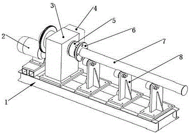
[0020] In order to overcome the low efficiency of manual welding, the weld joints formed by welding have many unfused and uneven welds, which affect the appearance quality of defects, this embodiment provides a pipe fitting circumferential seam automatic rotary welding tool, including a base 1. , The base is provided with a variable frequency motor 2, a transmission box 3 and an electric control cabinet 4, the variable frequency motor 2 is arranged on one side of the base 1, and the transmission box 3 and the electric control cabinet 4 are arranged side by side on the right side of the variable frequency motor 2 The transmission box 3 and the variable frequency motor 2 are connected by gear meshing, the electrical control cabinet 4 is electrically connected with the variable frequency motor 2, and the output shaft of the transmission box 3 is connected with a chuck 5.

[0021] The base 1 connects the variable frequency motor 2, the transmission box 3 and the electrical control cab...

Embodiment 2

[0026] On the basis of Embodiment 1, a support seat 8 is also provided on the base 1 on the side of the chuck 5 along the direction of the output shaft of the transmission box 3. There may be more than one support seat 8.

[0027] When in use, the flange 6 and the steel pipe 7 are installed on the chuck 5 first, and in this process, the support seat 8 plays an auxiliary supporting role for the steel pipe 7. The rotation speed of the variable frequency motor 2 is set through the electrical control cabinet 4, and the start or stop of the variable frequency motor 2 is controlled through the electrical control cabinet 4. After the variable frequency motor 2 is started, it drives the transmission box 3, and the transmission box 3 drives the chuck 5 to make a uniform rotation movement, and the chuck 5, which makes a uniform rotation movement, drives the flange 6 and the steel pipe 7 to make a uniform rotation movement synchronously. At this time, the welding operator only needs to aim...


PUM


Abstract

The invention belongs to the technical field of welding and specifically relates to an automatic spin welding tool for circular seams of pipe fittings. The automatic spin welding tool comprises a base. The base is provided with a variable frequency motor, a transmission case and an electric control cabinet. The variable frequency motor is arranged on one side of the base, and the transmission case and the electric control cabinet are arranged on the right side of the variable frequency motor side by side. The transmission case and the variable frequency motor are connected through a gear in an engaged manner. The electric control cabinet is electrically connected with the variable frequency motor. An output shaft of the transmission case is connected with a chuck. When the automatic spin welding tool for the circular seams of the pipe fittings is used for welding a flange and a steel pipe, the circular welding seams can be continuously formed, the number of welding connectors is reduced, and only one connector is arranged; and due to the fact that the flange and the steel pipe rotate at a constant speed, the circular welding seams formed during welding are relatively uniform and attractive. In addition, by means of the automatic spin welding tool for the circular seams of the pipe fittings, the production efficiency is greatly improved while the labor intensity of workers is reduced.

Description

Technical field [0001] The invention belongs to the technical field of welding, and in particular relates to a tool for automatic rotary welding of pipe joints. Background technique [0002] At present, the company’s welding work between flanges and steel pipes is mainly carried out by the company’s girth weld (internal) automatic welding device. During the welding process, the steel pipe needs to be rotated at a uniform speed, but most of them are simply used The motor drives the roller frame to rotate. This construction method has the following disadvantages: [0003] 1. The weld joint formed by welding due to the problem of speed has many defects such as unfusion; [0004] 2. Unstable rotation speed leads to uneven weld, which affects appearance quality; [0005] 3. Low work efficiency; [0006] 4. The labor intensity of workers who need to hoist back and forth is high. Summary of the invention [0007] The purpose of the present invention is to overcome the problems existing in th...

Claims


Application Information

Patent Timeline
Patent Type & Authority Applications(China)
IPC IPC(8): B23K37/053
CPCB23K37/0533Y02P70/10
Inventor 张清华程海强徐宗强张信义吴开强韩君昌韩梅
Owner 中电装备青岛豪迈钢结构有限公司
Why Eureka
Try Eureka