Novel clip clamping device

The invention relates to a clamping device and a clip technology, which is applied in the field of new clip clamping devices, and can solve the problems of low processing efficiency, affecting product quality and low position accuracy, and achieve the effects of improving processing efficiency, convenient use and reasonable process structure.

Inactive Publication Date: 2017-02-15
大连橡胶塑料机械有限公司
View PDF7 Cites 2 Cited by
  • Summary
  • Abstract
  • Description
  • Claims
  • Application Information

AI Technical Summary

Problems solved by technology

[0002] In the prior art, the clip clamping device is used for processing the clips of the synchronous stretching machine. The original clamping structure uses the clamping plate to directly press the clip on the working table of the machine tool. Under the action of the fastening bolt, the center of the fastening bolt is twisted, which causes the processed hole to shift; the outer surface of the clip is an unprocessed surface, and the hole is processed based on the unprocessed surface, so that the position accuracy of the processed hole is not high. The efficiency is not high; when the clips are combined and assembled, due to the difference in positional accuracy, the products produced after assembly are not uniform, which affects the quality of the products

Method used


Image

  • Novel clip clamping device
  • Novel clip clamping device
  • Novel clip clamping device

Examples


Embodiment Construction

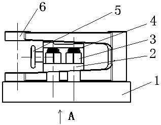
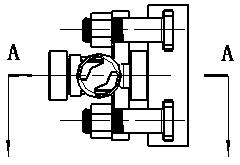
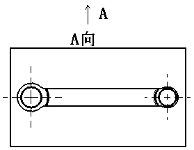
[0016] Such as Figure 1 to Figure 6 As shown, the new clip clamping device includes a base 1, a wedge iron 2, a handle 5 and a clip 6. The wedge iron 2 is fixedly connected to the T-shaped slot of the base 1 through a bolt 4 and a nut 3, and the bolt 4 passes through the base 1. The T-shaped slot on the top, the clip 6 and the wedge iron 2 are clamped on the base 1 through the nut 3, the handle 5 is connected with the wedge iron 2, the clip 6 is positioned on the long groove of the base 1, and the clip 6 is connected to the base 1 along the length direction. The T-slots are in the form of a single-station structure placed in parallel. The clips 6 can adopt a symmetrical or parallel-distributed double-station structure. The clips 6 can adopt a symmetrical and parallel-distributed multi-station structure. When used, the clips 6 are positioned On the long groove of the base 1, there is an arc line that can be aligned on the long groove. Use the handle 5 to connect the wedge iron...


PUM


Abstract

The invention discloses a novel clip clamping device which comprises a base (1), a wedge (2), a handle (5) and a clip (6). The wedge (2) is fixedly connected to a T-shaped groove formed in the base (1) through bolts (4) and nuts (3). The bolts (4) enable the clip (6) and the wedge (2) to be clamped on the base (1) through the T-shaped groove formed in the base (1) via the nuts (3). The handle (5) is connected with the wedge (2), and clip (6) is positioned to the long groove of the base (1). According to the novel clip clamping device, the problem that according to an original clamping structure, the position precision of a machined hole is poor is solved, and the quality of a produced product is low after clip assembling, the process structure is more reasonable, use is more convenient, and a dual-station and multi-station structure improves the machining efficiency.

Description

technical field [0001] The invention relates to a novel clip clamping device. Background technique [0002] In the prior art, the clip clamping device is used for processing the clips of the synchronous stretching machine. The original clamping structure uses the clamping plate to directly press the clip on the working table of the machine tool. Under the action of the fastening bolt, the center of the fastening bolt is twisted, which causes the processed hole to shift; the outer surface of the clip is an unprocessed surface, and the hole is processed based on the unprocessed surface, so that the position accuracy of the processed hole is not high. The efficiency is not high; when the clips are combined and assembled, due to the difference in positional accuracy, the products produced after assembly are not uniform, which affects the quality of the products. Contents of the invention [0003] The purpose of the present invention is to provide a novel clip clamping device ...

Claims


Application Information

Patent Timeline
IPC IPC(8): B23Q3/06
CPCB23Q3/062
Inventor 韩亚娜王德旭颜贵春范勋铭
Owner 大连橡胶塑料机械有限公司
Why Eureka
Try Eureka