Cutting device, substrate cutting method, and member for substrate mounting portion of cutting device

A cutting device and mounting part technology, applied in glass cutting devices, fine work devices, work accessories, etc., can solve the problems of insufficient pressing, residual cracking, uneven cutting edges, etc., to ensure the effect of legibility

Active Publication Date: 2019-12-10
MITSUBOSHI DIAMOND IND CO LTD
View PDF5 Cites 0 Cited by
  • Summary
  • Abstract
  • Description
  • Claims
  • Application Information

AI Technical Summary

Problems solved by technology

In the case of using such a transparent elastic body with a large thickness variation as a whole as it is in the mounting part of the cutting device, the force acting on the cutting blade will be uneven depending on the position, resulting in residual cracks and insufficient press-fitting. and other bad situations, it is difficult to reliably perform good cutting

Method used


Image

  • Cutting device, substrate cutting method, and member for substrate mounting portion of cutting device
  • Cutting device, substrate cutting method, and member for substrate mounting portion of cutting device
  • Cutting device, substrate cutting method, and member for substrate mounting portion of cutting device

Examples


Embodiment 1

[0096] The polishing treatment was performed on the initial elastic body 11β, and the effectiveness of the polishing treatment was confirmed. Specifically, as the initial elastic body 11β, prepare two silicone rubbers with a planar size of 60mm×310mm, a thickness of 3mm (both design values) and a hardness of 80° (as sample 1-1, sample 1-2 ) were polished using a #80 porous grindstone in a state in which they were each fixed to the adsorption plate of the flat grinding disc. For each sample, the irregularity cross section was measured using the laser displacement meter using the adsorption surface before and after the buffing as a reference. The maximum unevenness difference (the difference between the maximum height position and the minimum height position) obtained from the obtained cross section is as follows. also, Figure 8 It is a figure which shows the uneven|corrugated cross-section before and after the buffing process about the sample 1-2. In addition, in Figure 8...

Embodiment 2

[0101] Various evaluations were performed on the mounting portion member 1α using a transparent elastic body as the elastic body 11 .

[0102] Specifically, four silicone rubbers having a hardness of 60°, which were polished in the same manner as in Example 1, and finally polished were prepared, and different films 12 (film types A to D) were attached to each of them, and 4 films were produced. Members 1α for each mounting portion (as samples 2-1 to 2-4). The type, base material thickness, and total thickness of the film 12 used in each sample are as follows.

[0103] Sample 2-1: film type A (Gelpoly (registered trademark) GPD38-A02A04 manufactured by Panac Co., Ltd.), 38 μm, 53 μm;

[0104] Sample 2-2: film type B (Panaprotect (registered trademark) PX50T01A15 manufactured by Panac Co., Ltd.), 50 μm, 65 μm;

[0105] Sample 2-3: film type C (Panaprotect (registered trademark) GS38 manufactured by Panac Co., Ltd.), 38 μm, 53 μm;

[0106] Sample 2-4: film type D (OTT50 (regis...


PUM

PropertyMeasurementUnit
hardnessaaaaaaaaaa
thicknessaaaaaaaaaa
diameteraaaaaaaaaa

Abstract

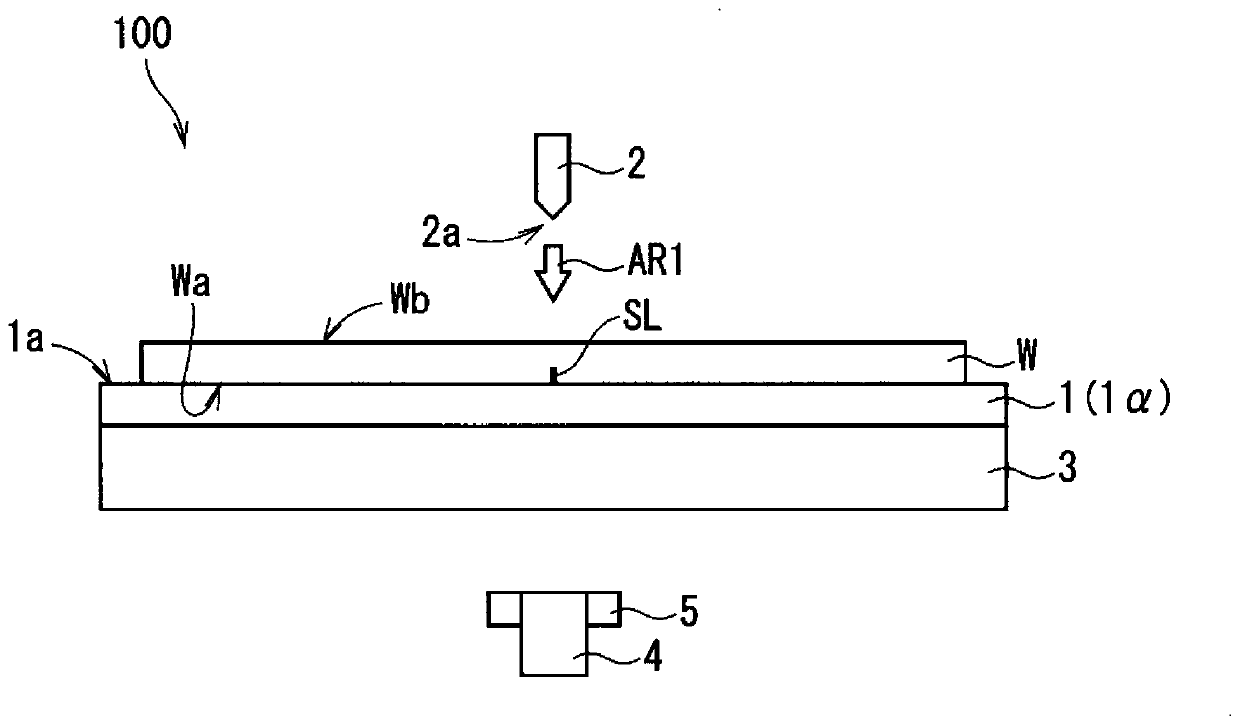
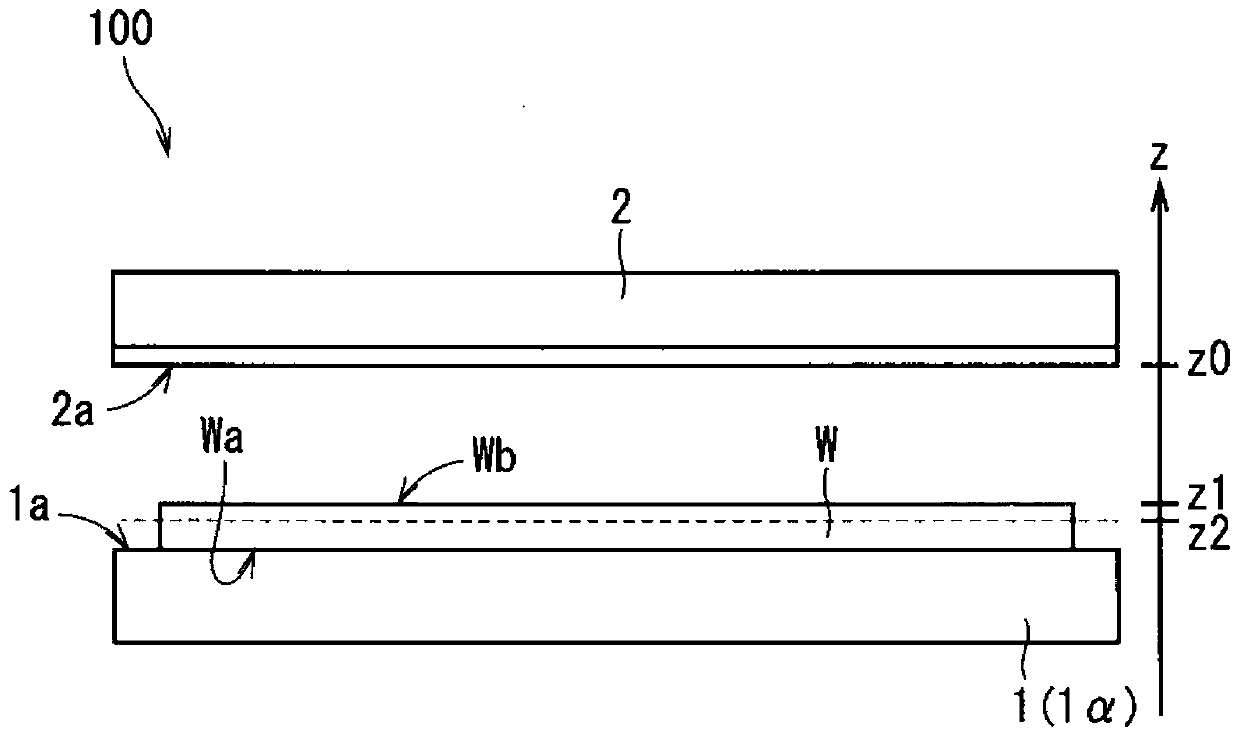
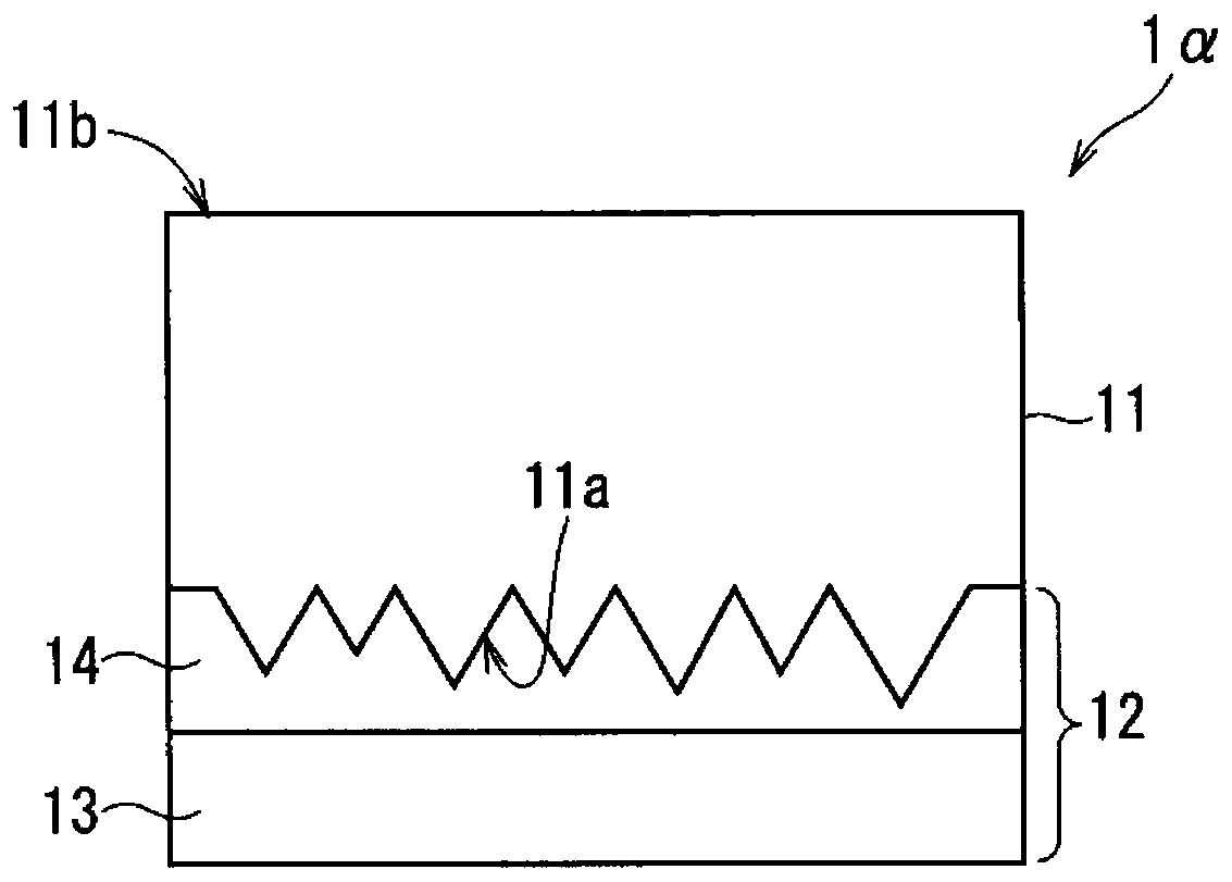
The present invention provides a member suitable for a substrate mounting portion of a cutting device that cuts a substrate along a scribe line. In a cutting device that cuts a substrate along a scribe line, a mounting portion including a plate-shaped transparent elastic body and a film is used as the mounting portion that mounts the substrate in a horizontal posture. The plate-shaped transparent elastic body By providing unevenness with a maximum unevenness difference of 50 μm or less on the first main surface, the vicinity of the first main surface becomes an opaque portion with a relatively lower transmittance of visible light than other parts, and the second main surface facing the first main surface is less than the second main surface. The first main surface is flat, the film is attached to the first main surface side of the elastic body, the non-applied surface is flat, and the transmittance of visible light in the thickness direction of the entire transparent elastic body in the state where the film is not attached is 30. % or less, the transmittance of visible light in the thickness direction is 60% or more, and the second main surface is used as the surface on which the substrate is placed.

Description

technical field [0001] The present invention relates to a cutting device for dividing a substrate, and more particularly to a structure of a mounting portion for placing a substrate during cutting. Background technique [0002] The manufacturing process of flat-panel display panels, solar cell panels, etc. generally includes a step of dividing substrates (mother substrates) made of brittle materials such as glass substrates, ceramic substrates, and semiconductor substrates. In such division, a method of forming a scribed line (scribed line) on the surface of the substrate using a scribed tool such as a diamond knife or a cutter wheel, and making a crack (vertical crack) along the substrate surface from the scribed line is widely used. Stretches in the thickness direction. When the scribe lines are formed, the vertical cracks may fully extend in the thickness direction and the substrate may be divided, but the vertical cracks may only partially extend in the thickness direct...

Claims


Application Information

Patent Timeline
Patent Type & Authority Patents(China)
IPC IPC(8): H01L21/67B28D1/22B28D7/04B28D5/04
CPCB28D1/22B28D5/0082B28D5/04B28D7/04Y02P40/57B28D1/20C03B33/033C03B33/037C03B33/03B26F3/002B26D7/20
Inventor 岩坪佑磨金平雄一村上健二
Owner MITSUBOSHI DIAMOND IND CO LTD
Why Eureka
Try Eureka