Highly efficient automatic glass forming device

An automatic forming, high-efficiency technology, applied in glass forming, glass remolding, glass tempering and other directions, can solve the problems of increased energy consumption, poor glass production quality, affecting glass quality, etc., and achieves slow production speed. , The effect of improving space utilization and improving maintenance convenience

Inactive Publication Date: 2017-02-15
金华市怡达玻璃机械有限公司
View PDF6 Cites 4 Cited by
  • Summary
  • Abstract
  • Description
  • Claims
  • Application Information

AI Technical Summary

Problems solved by technology

[0003] The temperature inside the furnace body in the traditional glass tempering furnace is very easy to emit, which not only increases the waste of energy consumption, but also greatly increases the temperature of the working environment of the operators, making the working environment of the operators extremely bad. At the same time, conventional The glass tempering furnace is not convenient for the operator to maintain and handle, and it cannot perform double-mode molding or processing of the glass. The production efficiency of glass tempering is low, and it is easy to appear uneven glass edges, poor glass production quality, and high production costs. production defect
[0004] And the published patent application number "201610398757.X", the patent name "a multi-mode forming glass tempering equipment", includes a feeding rack, an electric tempering furnace, a forming area, a flattening area, and an air cooling area arranged in sequence from left to right and the blanking area, but it does not solve the energy consumption problem and maintenance of the electric tempering furnace; although the forming area also describes the glass forming process and forming methods, it also shows the req

Method used


Image

  • Highly efficient automatic glass forming device
  • Highly efficient automatic glass forming device
  • Highly efficient automatic glass forming device

Examples


Embodiment Construction

[0033] The preferred embodiments of the present invention will be described in detail below in conjunction with the accompanying drawings, so that the advantages and features of the present invention can be more easily understood by those skilled in the art, so as to define the protection scope of the present invention more clearly.

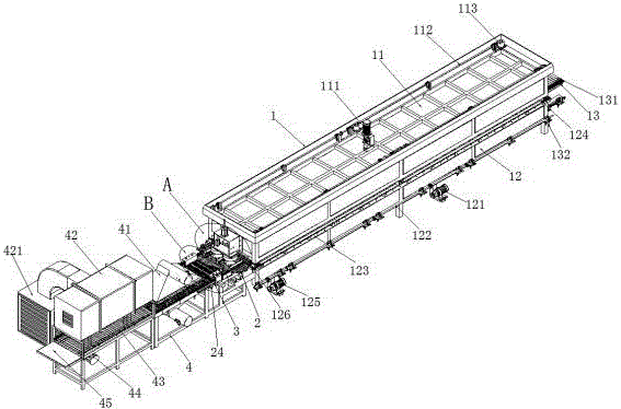
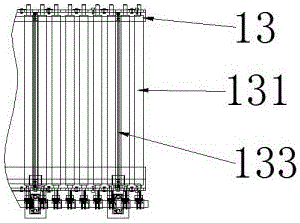
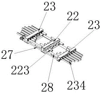
[0034] Such as Figure 1 to Figure 14 A high-efficiency glass automatic forming device shown includes a heating furnace 1, a forming frame 2, a conveying frame 3 and a cooling frame 4. The heating furnace 1 includes an upper furnace body 11, a lower furnace body 12 and a screw rod (not marked ), the upper furnace body 11 is provided with a lifting motor 111, a lifting rod 112 and a reduction motor 113, and the lower furnace body 12 is provided with a sheet feeding table 13, a first motor 132, a second motor 121, an acceleration motor 125, a conveying Rod 122 and placement plate 123, described molding frame 2 is provided with connecting frame 21, ...


PUM


Abstract

The invention provides a highly efficient automatic glass forming device which comprises a heating furnace, a forming rack, a conveying rack and a cooling rack. The heating furnace comprises a upper furnace body, a lower furnace body and a screw bar. The upper furnace body is provided with a lifting motor, a lifting bar and a decelerating motor. The lower furnace body is provided with a glass plate feeding table, a first motor, a second motor, an accelerating motor, a transmission bar and a positioning plate. The forming rack is provided with a connection rack, a model cylinder, a model, a pressing head, a pressing head cylinder and a positioning cylinder. The conveying rack is provided with a third motor, a bracket, a machine rack, a guiding rod, a guiding rack, a guiding rail, a rack, a stepping motor and the lifting cylinder. The cooling rack is provided with an extreme cooling wedge, a slow cooling bellow, a cooling fan , a fourth motor and a glass plate acceptance table; the device has the advantages of the capability of fast tempering, fast forming and fast cooling. These advantages grant conveniences to the manufacturer in the production, processing and maintenance and prevent the non-flatness in the edge of the heated and formed glass.

Description

technical field [0001] The invention relates to a high-efficiency glass automatic forming device. Background technique [0002] Glass tempering furnace, also known as glass tempering equipment, uses physical or chemical methods to form a compressive stress layer on the surface of the glass and a tensile stress layer inside; when the glass is subjected to external force, the compressive stress layer can offset part of the tensile stress and prevent the glass from breaking , to achieve the purpose of increasing the strength of the glass. [0003] The temperature inside the furnace body in the traditional glass tempering furnace is very easy to emit, which not only increases the waste of energy consumption, but also greatly increases the temperature of the working environment of the operators, making the working environment of the operators extremely bad. At the same time, conventional The glass tempering furnace is not convenient for the operator to maintain and handle, and i...

Claims


Application Information

Patent Timeline
IPC IPC(8): C03B23/03C03B27/04C03B35/16
CPCC03B23/03C03B27/04C03B35/163
Inventor 蔡念钢蔡悦
Owner 金华市怡达玻璃机械有限公司
Why Eureka
Try Eureka