
A drillable bolt device and construction method capable of realizing cross anchorage

A bolt and anchoring technology, which is applied to the installation of bolts, earthwork drilling, mining equipment, etc., can solve the problem of not being able to determine the anchoring position of the end of the bolt, increasing the safety hazards of construction workers, and failing to achieve the expected anchoring effect and other problems, to achieve the effect of simple and feasible installation procedure, improve the working conditions of workers, and reduce the anchorage length

Active Publication Date: 2018-07-06
HUNAN UNIV OF SCI & TECH
View PDF6 Cites 0 Cited by
  • Summary
  • Abstract
  • Description
  • Claims
  • Application Information

AI Technical Summary

Problems solved by technology

However, for the hollow resin anchor, due to its complicated construction technology, it not only prolongs the support time of the anchor, but also increases the safety hazards of the construction workers; Determine the anchoring position at the end of the anchor rod, but the expected anchoring effect cannot be achieved
In addition, due to the harsh construction environment of the anchor bolt, the anchoring agent and the injected cement slurry are often corroded and oxidized by groundwater and air rich in various chemical components, resulting in a greatly reduced anchorage strength; and the anchoring agent has a certain fluidity, A certain degree of overflow will also occur during the installation of the anchor bolt and after the installation is affected by the disturbance of the adjacent working area, and the grouting anchor bolt is also often not full during the grouting process.
Due to the existence of these problems, a large area of ​​deformation and cracking will be formed on the support part in the long run, which will increase the maintenance cost in the later period

Method used


Image

  • A drillable bolt device and construction method capable of realizing cross anchorage
  • A drillable bolt device and construction method capable of realizing cross anchorage
  • A drillable bolt device and construction method capable of realizing cross anchorage

Examples


Embodiment Construction

[0029] The present invention will be described in further detail below in conjunction with the accompanying drawings.

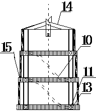
[0030] Such as Figure 1-2 As shown, it is a schematic diagram of the overall structure of the anchor rod device of the present invention. The anchor rod of the present invention is composed of a transmission rod 1, a fixed nut 2, a nut 3, a tray 4, a hollow anchor rod 5, a driving gear 6, a fixed rod 7, a bearing 8, an anchor Rod bit 9 and three telescoping bits. In the present invention, the external drilling rig transmits telescopic power to the inside of the bolt through the transmission rod 1 .

[0031] The tray 4 and the fixing nut 2 are provided with a circular hole to allow the transmission rod 1 to pass through and fix the position of the transmission rod 1 . The tray 4 is installed on the rear end of the hollow anchor rod 5 through the nut 3, so that the transmission rod 1 extends into the hollow anchor rod 5 and is connected with the driving gear...


PUM


Abstract

The invention discloses a drillable anchor rod device capable of being anchored in a crossed mode and a construction method. The drillable anchor rod device capable of being anchored in the crossed mode comprises a transmission rod, a tray, a hollow anchor rod, a transmission gear, a fixing rod, bearings, an anchor rod drill and telescopic drills. The transmission rod is connected with a driving gear in the hollow anchor rod. The tray is installed at the rear end of the hollow anchor rod, and the drill rod drill is installed at the front end of the hollow anchor rod. The multiple telescopic drills are installed on the lateral wall of the hollow anchor rod through the bearings. The multiple telescopic drills are arranged on the lateral wall of the hollow anchor rod of the drillable anchor rod device capable of being anchored in the crossed mode, the telescopic drills can drill holes in surrounding rock, crossed anchoring is achieved, the anchoring quality is good, the anchoring length is effectively reduced, and supporting cost is reduced.

Description

technical field [0001] The invention relates to a drillable bolt device and a construction method capable of realizing cross anchorage. Background technique [0002] With the continuous development of modern economy and science and technology, underground engineering construction, especially shaft engineering, continues to develop deep. At the same time, the phenomenon of large deformation of shafts and chambers under complex stress environments can be seen everywhere. Reasonable support for excavated roadways, chambers, and tunnel surrounding rocks is an important means to prevent deformation of surrounding rocks. The current support is based on bolt support and the combination of bolt support and bolt support, which has become a main support method in today's shaft engineering and tunnel construction. [0003] The development of anchors has undergone several changes. Steel structure anchors have high shear and tensile strength, remarkable construction effects, and low co...

Claims


Application Information

Patent Timeline
Patent Type & Authority Patents(China)
IPC IPC(8): E21D20/00E21D21/00
CPCE21D20/003E21D21/00
Inventor 余伟健吴根水王卫军
Owner HUNAN UNIV OF SCI & TECH
Learn More