
A fan power system

A technology for power systems and fans, applied in the directions of machines/engines, mechanical equipment, liquid fuel engines, etc., can solve the problems of limited functional capacity of the fan system, and achieve the effects of compact structure, large air volume, and enhanced aerodynamic performance.

Active Publication Date: 2018-11-20
NINGBO FOTILE KITCHEN WARE CO LTD
View PDF15 Cites 1 Cited by
  • Summary
  • Abstract
  • Description
  • Claims
  • Application Information

AI Technical Summary

Problems solved by technology

This kind of centrifugal fan has wide main blades and narrow splitter blades. The function of splitter blades is to reduce inlet blockage and reduce losses. However, since the splitter blades are set in the middle of the flow channel of the main blades, the It is determined by the number of main blades, and the splitter blades and the main blades share the same inlet, so the splitter blades have very limited ability to strengthen the entire fan system

Method used


Image

  • A fan power system
  • A fan power system
  • A fan power system

Examples


Embodiment 1

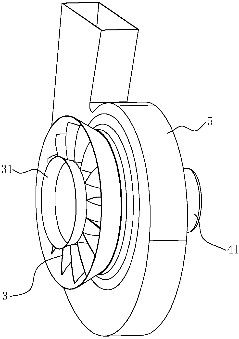
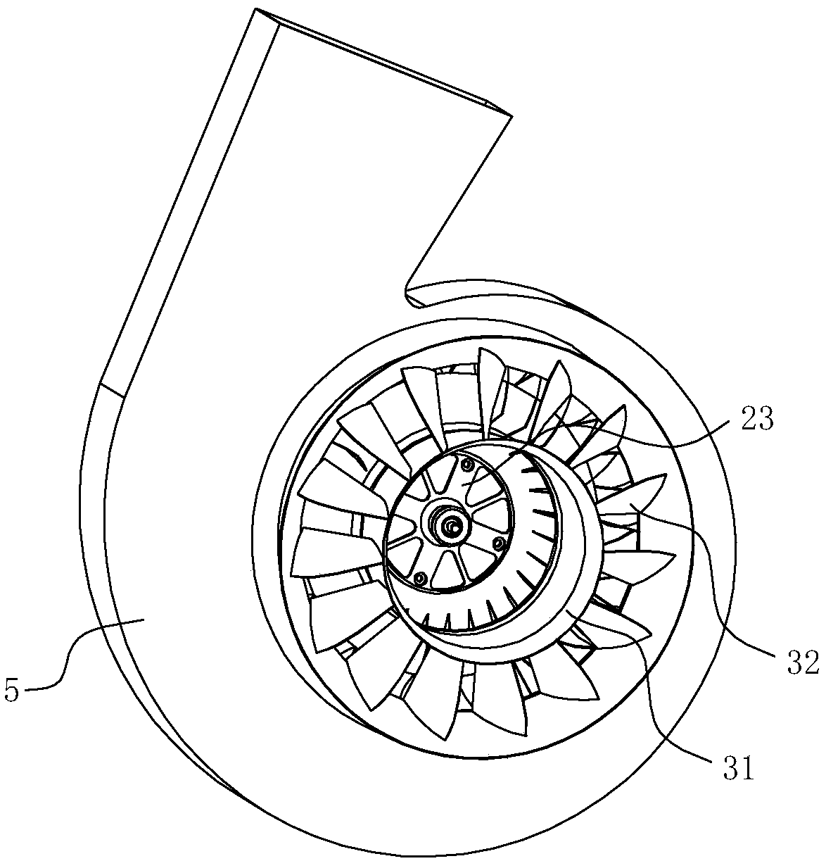
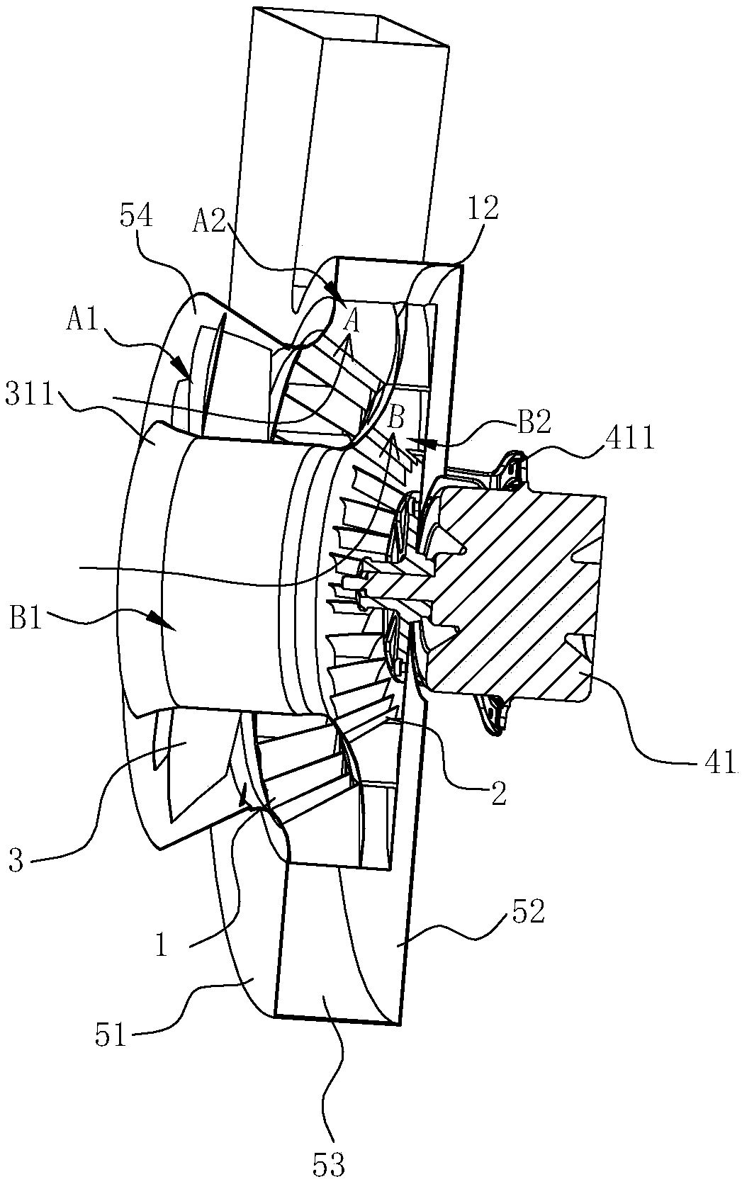
[0041] see Figure 1 ~ Figure 4 , a fan power system, including a centrifugal fan, an axial flow fan 3, a first motor 41 and a volute 5, the centrifugal fan includes a first centrifugal fan 1 and a second centrifugal fan 2 coaxially arranged side by side in front and rear, the shaft The flow fan 3 is connected in series on the front side of the first centrifugal fan 1, thus making the fan power system form two airflow channels: the main airflow channel, image 3 As indicated by the middle arrow A, and the auxiliary airflow channel, image 3 Indicated by the middle arrow B.

[0042]The above-mentioned first centrifugal fan 1 , second centrifugal fan 2 and axial flow fan 3 are driven by the same first motor 41 . The volute 5 includes a front cover 51, a rear cover 52, and an intermediate cover 53 between the front cover 51 and the rear cover 52. An air inlet 511 is formed on the front cover 51 of the volute 5, and the front cover On the front side of the plate 51 , at the pos...

Embodiment 2

[0052] see Figure 13 , in this embodiment, the difference from the first embodiment above is that in order to better match the main air flow channel A and the auxiliary air flow channel B, and further enhance the fan's ability to work on the air flow, the hub 31 is located behind the front end 311 The peripheral wall of the side part extends obliquely, so that the shape of the hub 31 is a cone whose outer diameter gradually increases from the front to the rear, thereby making the cross-sectional area of ​​the main airflow channel A gradually decrease from the front to the rear, so that the airflow can be accelerated after entering , to maximize the working capacity of the front axial flow fan 3 .

Embodiment 3

[0054] see Figure 14 , in this embodiment, the difference from the first embodiment above is that in order to better match the main air flow channel A and the auxiliary air flow channel B, and further enhance the fan's ability to work on the air flow, the hub 31 is located behind the front end 311 The peripheral wall of the side portion extends in a curved shape, so that the shape of the hub 31 is a bionic curve shape in which the outer diameter gradually increases from the front to the rear, thereby making the cross-sectional area of ​​the main airflow channel A gradually decrease from the front to the rear, so that the airflow enters the Finally, it can be accelerated to maximize the working ability of the front axial flow fan 3.


PUM


Abstract

The invention discloses a fan power system which comprises a centrifugal fan, an axial flow fan and a volute; the axial flow fan is arranged on the front side of the centrifugal fan; the centrifugal fan and the axial flow fan are both arranged in the volute; the centrifugal fan is composed of a first centrifugal fan and a second centrifugal fan which are coaxially arranged in parallel from front to back; the first centrifugal fan is composed of first blades and a first chassis used for placing the first blades; the second centrifugal fan is composed of second blades and a second chassis used for placing the second blades; the axial flow fan is composed of third blades and a hub used for placing the third blades; the back end of the hub and the first chassis form an integral or split structure without an interval; the first blades are at least locally arranged on the outer sides of the third blades respectively on a vertical axial projection of the fan power system; the hub is in a hollow shape with openings formed in the front end and the back end respectively; the volute, the axial flow fan, the first centrifugal fan and the second centrifugal fan are matched with one another to form a main air flow channel and an auxiliary air flow channel which are separated from each other.

Description

technical field [0001] The invention relates to a fan, in particular to a fan power system. Background technique [0002] The power system is used in various industrial occasions. The core component in the middle is the fan. Different fan system types can be selected according to the pipe network used. When the application requires strong power, low noise, and high Efficiency, compact structure, and a single fan type are often difficult to meet the requirements of use, so some new design types can be used to increase the working ability of the airflow and improve the internal flow. [0003] For example, a Chinese patent with application number 201410674277.2 discloses a ventilation device, which includes a centrifugal fan and an axial flow fan connected in the air inlet direction, wherein the centrifugal fan is used to increase the wind pressure of the air entering the ventilation device, and the axial flow fan is used To increase the volume of air entering the ventilation ...

Claims


Application Information

Patent Timeline
Patent Type & Authority Patents(China)
IPC IPC(8): F04D25/08F04D25/16F04D29/32F04D29/44F04D29/42F04D29/66
CPCF04D25/08F04D25/166F04D29/325F04D29/329F04D29/4226F04D29/441F04D29/666
Inventor 黄友根李志峰陈浩辉边乐超茅忠群诸永定李斌
Owner NINGBO FOTILE KITCHEN WARE CO LTD
Learn More