Manual butterfly valve of center control line
A central control line, butterfly valve technology, applied in the direction of lift valve, valve device, engine components, etc., can solve the problems of small pressure and working range, easy damage of rubber rings, difficult to repair or replace, etc., to achieve low cost, simple replacement, The effect of easy maintenance
- Summary
- Abstract
- Description
- Claims
- Application Information
AI Technical Summary
Problems solved by technology
Method used
Image

Examples
Embodiment Construction
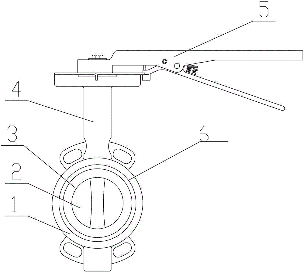
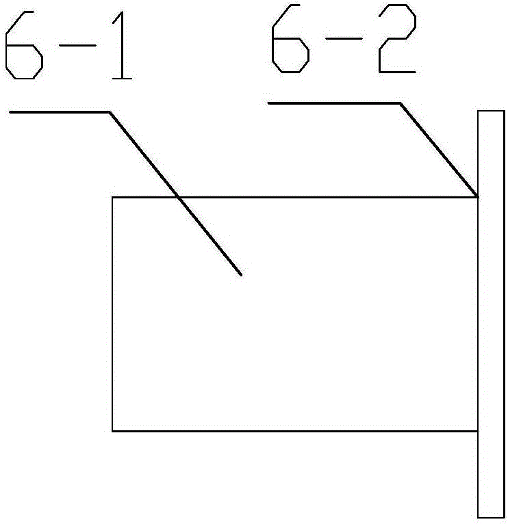
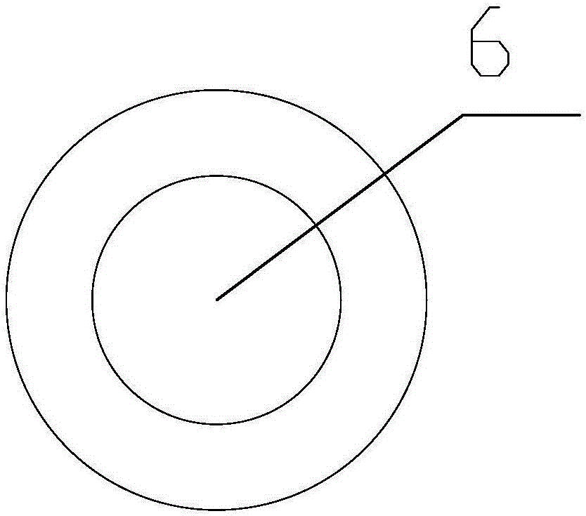
[0013] Such as Figure 1-3 Shown: the central control line manual butterfly valve, including valve seat 1, valve plate 2, valve seat liner 3, valve stem 4 and handle 5; the valve seat 1 is provided with a valve seat liner 3, and the valve plate 2 passes through the valve The seat ring 3 is arranged in the valve seat 1; the valve plate 2 is connected to the valve stem 4, and the valve stem 4 is connected to the handle 5; an isolation bush 6 is also provided between the valve seat ring 3 and the valve seat 1 , The isolation bushing 6 includes a sleeve 6-1 and an extension 6-2; the extension 6-2 takes the center of the sleeve 6-1 as the center and extends radially toward the sleeve 6-1 to form The center of the sleeve 6-1 is a ring with the center of the circle.
[0014] The valve seat lining ring 3 is made of the same material as the inner wall of the valve seat 1. The valve seat ring 3 and the valve seat 1 form a clearance fit. The width of the extension 6-2 is greater than the...
PUM
 Abstract
Description
Claims
Application Information
 - R&D
- Intellectual Property
- Life Sciences
- Materials
- Tech Scout
- Unparalleled Data Quality
- Higher Quality Content
- 60% Fewer Hallucinations
Browse by: Latest US Patents, China's latest patents, Technical Efficacy Thesaurus, Application Domain, Technology Topic, Popular Technical Reports.
© 2025 PatSnap. All rights reserved.Legal|Privacy policy|Modern Slavery Act Transparency Statement|Sitemap|About US| Contact US: help@patsnap.com