Circuit and method for controlling hydraulic valve flow

A technology for controlling circuits and hydraulic valves, applied in the direction of valve operation/release devices, valve details, valve devices, etc., can solve problems such as unsuitable for general design, single control object, easy to be cracked, etc., and achieve control parameter confidentiality Strong, real-time monitoring parameters, stable static characteristics

Active Publication Date: 2017-02-15
BEIJING RES INST OF PRECISE MECHATRONICS CONTROLS
View PDF5 Cites 3 Cited by
  • Summary
  • Abstract
  • Description
  • Claims
  • Application Information

AI Technical Summary

Problems solved by technology

However, the existing control method does not have the ability of real-time debugging, and at the same time cannot monitor the working parameters in real time. The measurement and control system cannot understand the working status of each closed-loop of the current hydraulic valve. Due to the use of analog control, all control parameters are given in the form of resistance and capacitance. , for hydraulic valves of the same series and different models, it is necessary to adjust different resistance and capacitance values, or change the circuit design, which is not suitable for general design, the control object is single, and the control parameters are displayed in the form of resistance and capacitance, which is easy to be cracked and does not have digital Control Method

Method used


Image

  • Circuit and method for controlling hydraulic valve flow
  • Circuit and method for controlling hydraulic valve flow
  • Circuit and method for controlling hydraulic valve flow

Examples


Embodiment Construction

[0055] The present invention will be described in further detail below with reference to the accompanying drawings.

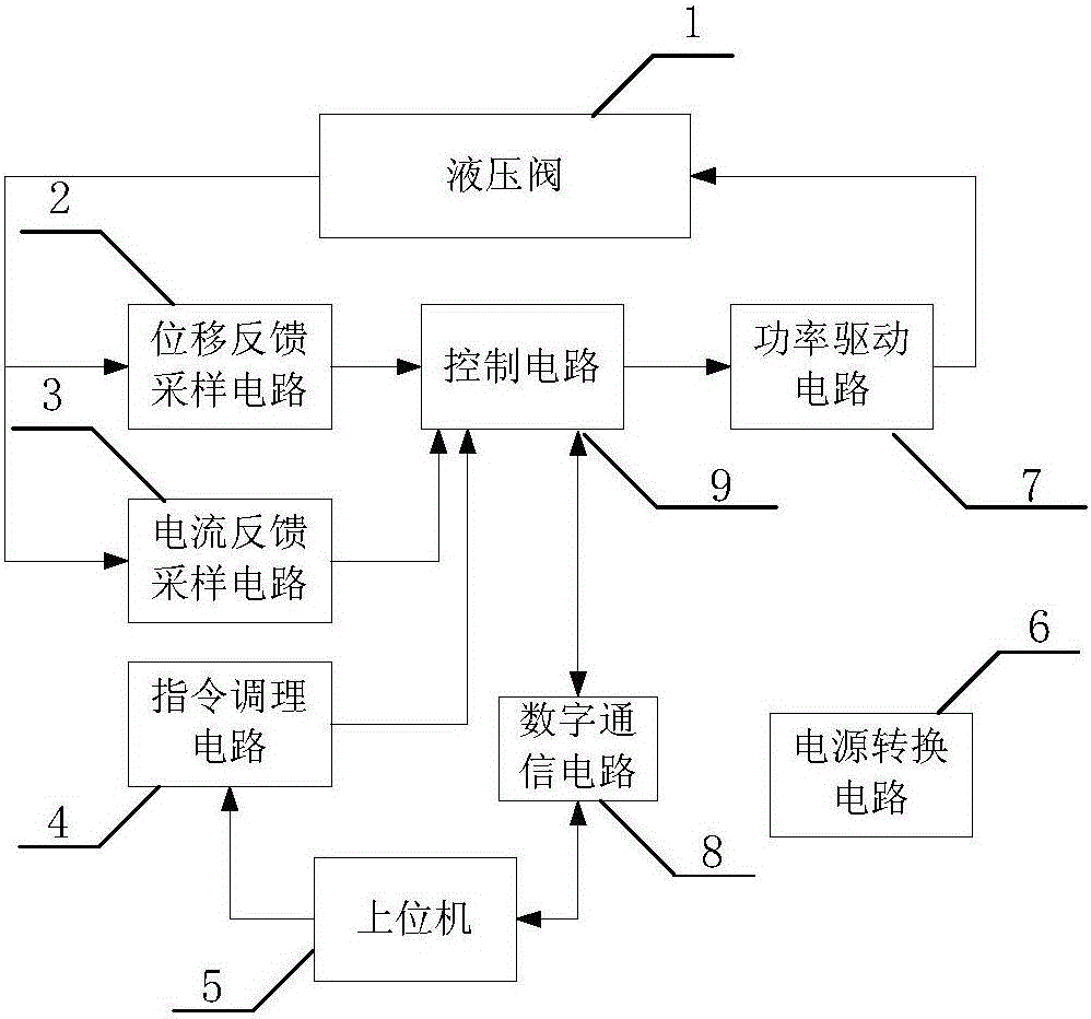
[0056] like figure 1 As shown in the figure, a circuit for controlling the flow rate of a hydraulic valve includes a hydraulic valve 1, a displacement feedback sampling circuit 2, a current feedback sampling circuit 3, an instruction conditioning circuit 4, a host computer 5, a power conversion circuit 6, a power drive circuit 7, and digital communication. circuit 8, control circuit 9;

[0057] Hydraulic valve 1 transmits its spool displacement signal and valve coil current signal to displacement feedback sampling circuit 2 and current feedback sampling circuit 3 respectively; displacement feedback sampling circuit 2 receives the spool displacement signal transmitted by hydraulic valve 1 and processes it into control circuit 9 The voltage signal can be received, and the voltage signal is transmitted to the control circuit 9; the current feedback sampling circu...


PUM


Abstract

The invention discloses a circuit and a method for controlling hydraulic valve flow. Through a digital-controlling circuit, the hydraulic valve flow controlled in a digital mode is achieved. The amplitude bandwidth responding to the hydraulic valve flow is bigger than 70 Hz, phase bandwidth is bigger than 60 Hz, distinguishability is smaller than 0.1%, and the overlap amount is smaller than 0.5%. Compared with other hydraulic valves, the amplitude-frequency response is wide and statistic characteristic is steadier. Through a digital communication circuit, the controller area network (CAN) bus communication between a control circuit and an upper computer is achieved, and a product has real-time adjustment, real-time monitoring parameter, a wide using range and high security of controlling parameter.

Description

technical field [0001] The invention relates to a circuit and a method for controlling the flow rate of a hydraulic valve, and belongs to the field of automatic control. Background technique [0002] The control method of the pilot stage jet valve usually uses an analog device for closed-loop control, calculates the error between the command and the feedback, and then amplifies it through the amplifier and outputs it to the drive unit to drive the pilot stage coil, and finally realize the control of the hydraulic valve. However, the existing control method does not have the ability of real-time debugging, and at the same time, it cannot monitor the working parameters in real time. The measurement and control system cannot understand the current working status of each closed-loop hydraulic valve. Due to the use of analog control, all control parameters are given in the resistance-capacitance method. , For different types of hydraulic valves of the same series, it is necessary...

Claims


Application Information

Patent Timeline
Patent Type & Authority Applications(China)
IPC IPC(8): F16K31/02
CPCF16K31/02
Inventor 何雨昂袁建光张华樊茜陈鹏姜迪开
Owner BEIJING RES INST OF PRECISE MECHATRONICS CONTROLS
Why Eureka
Try Eureka