

Candle lamp
A technology of candle lights and LED lights, which is applied in the field of candle lights, can solve problems such as inability to project images or patterns, inability to produce optical effects, and single light source mode, so as to increase entertainment, increase the atmosphere of the space environment, and achieve good technical effects
- Summary
- Abstract
- Description
- Claims
- Application Information
AI Technical Summary
Problems solved by technology
Method used
Image

Examples
Embodiment 1
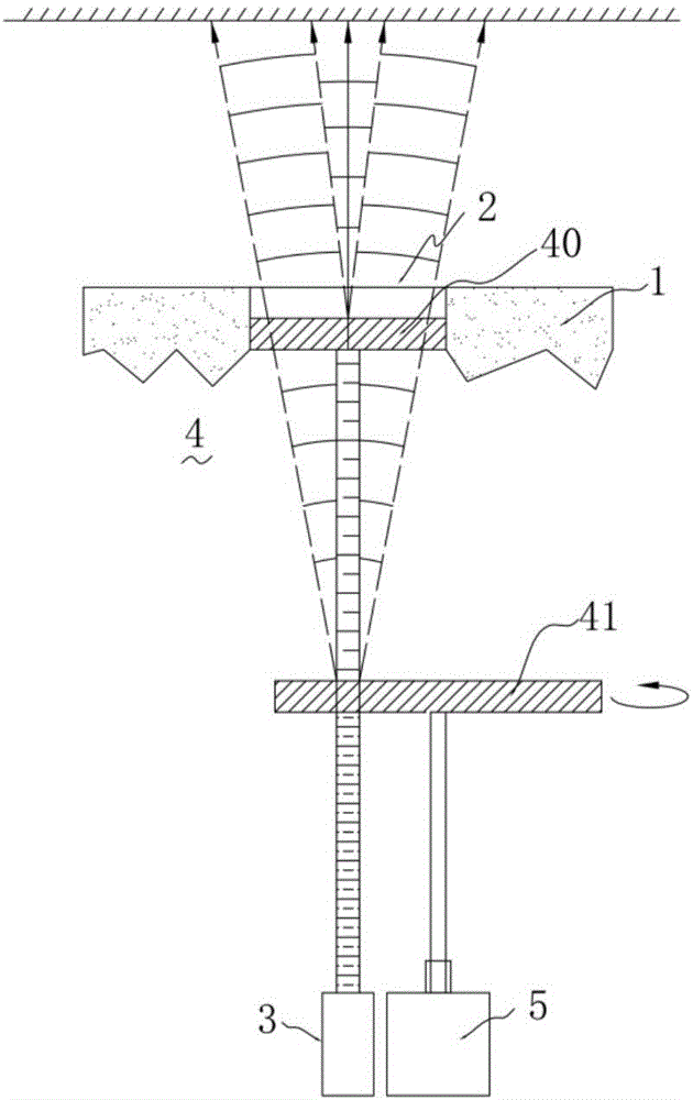
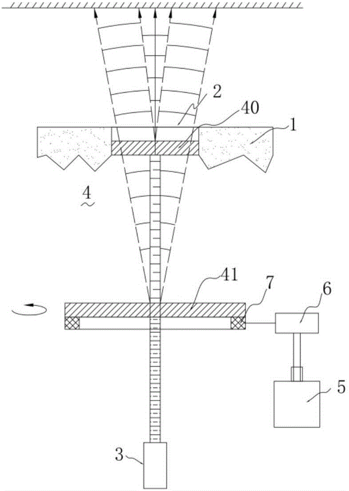
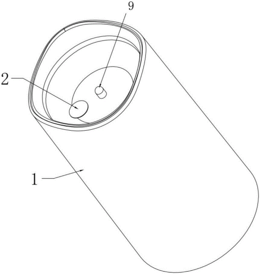
[0039] Such as image 3 , Figure 4 and Figure 5 , Figure 6 As shown, the laser and the light exit window 2 are arranged in a one-to-one correspondence, and the grating sheet 4 is correspondingly arranged in the direction of the light path between the laser and the light exit window 2 .
[0040] Such as image 3 and Figure 4As shown, one laser is set, and one corresponding light exit window 2 is also set. The grating sheet 4 includes a static grating sheet 40 arranged at the light exit window 2, and a dynamic grating sheet 41 arranged between the static grating sheet 40 and the laser. , the outer periphery of the laser is sleeved and connected with a heat sink 30, and the dynamic grating sheet 41 is connected with a motor rotating mechanism that drives it to rotate freely. 41 There is a rotating base 7 at the bottom, the rotating base 7 meshes with the gear rotating mechanism 6, the gear rotating mechanism 6 is connected with the rotating motor 5, the rotating motor 5 ...
Embodiment 2
[0051] Such as Figure 9 to Figure 13 As shown, there are at least two lasers 3, and there is only one light exit window 2. An optical path direction adjustment mechanism is arranged between the laser and the light exit window. The laser beams emitted by the lasers 3 at different positions pass through the optical path direction adjustment mechanism. Gather in the space area corresponding to the grating sheet 4, and emit through the grating sheet 4 to generate a diffracted beam.
[0052] The lasers are set to two, respectively the first laser and the second laser that are vertical in space, and the laser beams emitted by the first laser and the second laser are linearly polarized light, and the optical path direction adjustment mechanism includes a beam combining mirror, and the beam combining mirror And the grating sheet is correspondingly arranged on the light path direction between the light exit window and the first laser, the beam combiner includes a reflective mirror sur...
Embodiment 3
[0058] Such as Figure 14 As shown, this embodiment is basically similar in structure and principle to the above-mentioned Embodiment 1 and Embodiment 2, the difference is that a plurality of grating units 410 are provided on the dynamic grating sheet 41 , and each grating unit 410 forms a different pattern correspondingly. When the dynamic grating plate 41 is rotating, the laser beam emitted by the laser will form different patterns and emit with the rotation of the dynamic grating plate 41 .
[0059] In addition, in the above embodiments 1, 2 and 3, the periphery of the LED lamp of the candle lamp is also covered with an imaging lens. The combination of LED lights and laser lights makes it possible to use LED lights to play the role of lighting and embellishment when the laser is projecting images or patterns, increasing the atmosphere of the space environment, and making the overall technical effect better. In addition, The outer periphery of the LED lamp is also covered w...
PUM
 Abstract
Description
Claims
Application Information