
Device and method for measurement of aspheric compensator transmission wavefront equation

A technology of measuring device and measuring method, which is applied in the field of optical detection, can solve problems such as aspheric deviation from the design value and the influence of the optical system, and achieve the effects of low cost, high measurement accuracy and avoiding serious influence

Inactive Publication Date: 2017-02-15
CHANGCHUN INST OF OPTICS FINE MECHANICS & PHYSICS CHINESE ACAD OF SCI
View PDF6 Cites 9 Cited by
  • Summary
  • Abstract
  • Description
  • Claims
  • Application Information

AI Technical Summary

Problems solved by technology

In the detection process, the aspheric compensator is a key factor that limits the detection accuracy; if there is a problem with the compensator (such as a lens curvature radius processing error or a lens interval assembly error), it will directly cause the processed aspheric surface to deviate from the design value, thus seriously affecting the optical system

Method used


Image

  • Device and method for measurement of aspheric compensator transmission wavefront equation
  • Device and method for measurement of aspheric compensator transmission wavefront equation
  • Device and method for measurement of aspheric compensator transmission wavefront equation

Examples


Embodiment Construction

[0021] In order to make the object, technical solution and advantages of the present invention clearer, the present invention will be described in further detail below in conjunction with specific embodiments and with reference to the accompanying drawings.

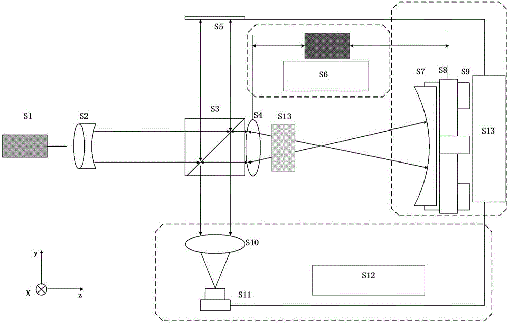
[0022] see figure 1 , figure 1 Shows the measurement device of the transmitted wavefront equation of the aspheric compensator according to the embodiment of the present invention, the measurement device includes: a phase-shifting interferometer, a ranging interferometer and a reference spherical component; wherein,

[0023] Phase-shifting interferometer includes: frequency-stabilized laser S1, collimating beam expander system S2, beam splitting prism S3, converging mirror group S4, phase-shifting reference surface S5, imaging mirror S10, detector S11 and image acquisition unit S12;

[0024] The reference sphere assembly includes: reference sphere S7, clamping mechanism S8, multi-dimensional adjustment table S9 and six-di...


PUM


Abstract

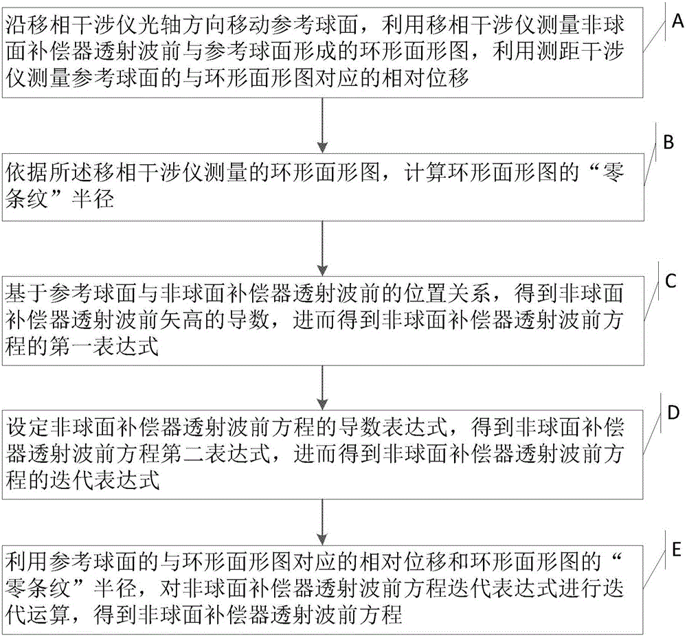
The present invention provides a device and method for measurement of an aspheric compensator transmission wavefront equation. The device comprises a phase shift interferometer, a distance measurement interferometer and a reference sphere assembly. The aspheric compensator is arranged between the phase shift interferometer and the reference sphere assembly, and the aspheric compensator, the phase shift interferometer and the reference sphere assembly are coaxially arranged; the reference sphere assembly is moved along the direction of an optical axis, and the reference sphere assembly and the aspheric compensator form an annular surface-shaped figure; and the measurement is performed through the distance measurement interferometer referring to the relative displacement of the sphere assembly, and the phase shift interferometer employs the annular surface-shaped figure and the relative displacement to calculate the aspheric compensator transmission wavefront equation. The device and method for measurement of the aspheric compensator transmission wavefront equation can realize the measurement of the aspheric compensator transmission wavefront so as to ensure the correction of the aspheric compensator prior to the aspheric surface processing, avoid that the aspheric compensator processing error causes severe influence on a final optical system; and moreover, the measurement precision of the measurement method is high, the cost of the measurement device is low, and the device and method for measurement of the aspheric compensator transmission wavefront equation are convenient to operate.

Description

technical field [0001] The invention relates to the technical field of optical detection, in particular to a measuring device and method for the transmission wavefront equation of an aspheric compensator. Background technique [0002] In optical design, the only degree of freedom that can be optimized for a single spherical surface is the radius of curvature; in addition to the radius of curvature of the apex, an aspherical surface also has quadric surface constants and higher-order coefficients. Since the aspheric surface has more degrees of freedom in design than the spherical surface, in many optical systems, aspheric elements are commonly used to reduce the complexity of the system and improve the imaging quality of the system. [0003] At present, for the detection of high-precision aspheric surfaces, most of them use the zero compensation method, that is, using compensating mirrors or computer-generated holograms (Computer-Generated Holograms, CGH) as compensators to c...

Claims


Application Information

Patent Timeline
IPC IPC(8): G01M11/02
CPCG01M11/0271
Inventor 高松涛苗二龙武东城隋永新杨怀江
Owner CHANGCHUN INST OF OPTICS FINE MECHANICS & PHYSICS CHINESE ACAD OF SCI
Learn More