
A TDR touch screen and a touch scanning locating method

A positioning method, touch scanning technology, applied in the direction of instrument, electrical digital data processing, input/output process of data processing, etc., can solve the high requirements of measurement impedance change algorithm, the distribution resistance of transmission line can not be ignored, the signal attenuation is large, etc. problem, to reduce the amplitude of the input step signal level, which is beneficial to the thinning and cost, and the effect of shortening the length of the wire

Inactive Publication Date: 2017-02-15
GUANGZHOU SHIYUAN ELECTRONICS CO LTD
View PDF5 Cites 0 Cited by
  • Summary
  • Abstract
  • Description
  • Claims
  • Application Information

AI Technical Summary

Problems solved by technology

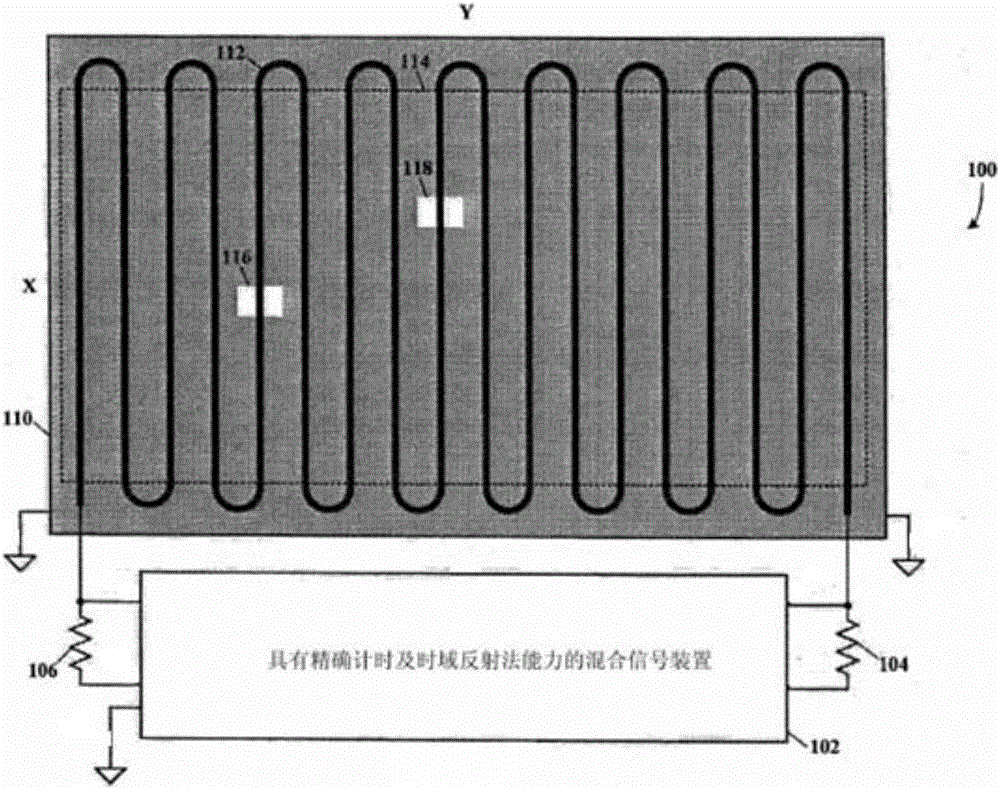
[0006] 1. The signal attenuation reflected at the end of the transmission line is large, requiring a very high input step signal level, resulting in increased radiation; at this time, the distributed resistance of the transmission line cannot be ignored, and additional variable calculation is required;
[0007] 2. The serpentine transmission line will have multiple large-angle inflection points, and its impedance will also have multiple mutation points, which requires a higher algorithm for measuring impedance changes

Method used


Image

  • A TDR touch screen and a touch scanning locating method
  • A TDR touch screen and a touch scanning locating method
  • A TDR touch screen and a touch scanning locating method

Examples


Embodiment Construction

[0055] The following will clearly and completely describe the technical solutions in the embodiments of the present invention with reference to the accompanying drawings in the embodiments of the present invention. Obviously, the described embodiments are only some, not all, embodiments of the present invention. Based on the embodiments of the present invention, all other embodiments obtained by persons of ordinary skill in the art without creative efforts fall within the protection scope of the present invention.

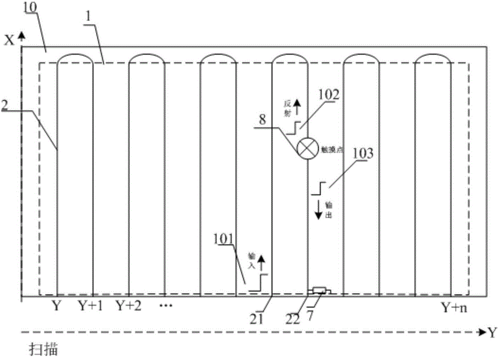
[0056] see figure 2 , figure 2 It is a schematic structural diagram of the touch screen of a preferred embodiment of the TDR touch screen provided by the present invention. The TDR touch screen includes a touch area 1 and several parallel and mutually independent U-shaped wires 2 distributed in the touch area 1 . Each of the U-shaped wires 2 is a transparent U-shaped wire 2 , and the distance between each of the U-shaped wires 2 and the adjacent U-shaped wires ...


PUM


Abstract

The invention provides a TDR touch screen comprising a touch area and a plurality of parallel U-shaped wires which are arranged in the touch area and are independent of one another. An insulation layer is arranged over the U-shaped wires. The TDR touch screen also comprises a signal transmitter, a reflection signal detector and a scanning drive circuit; the input ends of the U-shaped wires are connected with the signal transmitter and the reflection signal detector; the signal transmitter is connected with the scanning drive circuit. The invention also provides a touch scanning locating method suitable for the TDR touch screen. The method is characterized in that the scanning drive circuit drives the signal transmitter to transmit step signals to the input ends of the U-shaped wires successively and the reflection signal detector receives reflection signals of the input ends successively and correspondingly; touch positions are located based on the time delay from the input of the step signals to the reception of the reflection signals. According to the invention, multi-point touch control is realized, the touch control algorithm difficulty is reduced, and the touch control locating precision is improved.

Description

technical field [0001] The invention relates to the field of touch screens, in particular to a time-domain reflectometry (TDR)-based scanning touch screen and a touch scanning positioning method. Background technique [0002] Existing touch screens mainly include resistive touch screens, capacitive touch screens, and infrared touch screens. [0003] Resistive touch screens are mainly used in low-end products, usually only have a single touch function. Capacitive touch screens are widely used in various electronic products, but there are problems such as complex manufacturing process and high cost when applied to super-large-sized products, so large-sized products usually use infrared touch screens. Infrared touch screens need to arrange infrared emitting tubes and infrared receiving tubes around the screen, resulting in large volume and thickness, and the accumulation of dust will cause abnormal touch sensing. [0004] In order to solve the above problems, the prior art ad...

Claims


Application Information

Patent Timeline
Patent Type & Authority Applications(China)
IPC IPC(8): G06F3/045G06F3/047G06F3/041
CPCG06F3/045G06F3/0416G06F3/047
Inventor 刘贵翔
Owner GUANGZHOU SHIYUAN ELECTRONICS CO LTD
Learn More