
Optical coupling device

An optical coupling device and optical receiving technology, which is applied in the direction of semiconductor devices, electrical components, circuits, etc., can solve the problems of enlarging the package, increasing the distance of the optical receiving element, and wrongly transmitting signals, etc.

Active Publication Date: 2017-02-15
KK TOSHIBA
View PDF9 Cites 0 Cited by
  • Summary
  • Abstract
  • Description
  • Claims
  • Application Information

AI Technical Summary

Problems solved by technology

[0005] In such an optical coupling device, light from a light-emitting element of one optical coupling group is easily received by a light-receiving element of another optical coupling group, and a so-called crosstalk in which a signal is erroneously transmitted is generated.
Crosstalk can be prevented by increasing the distance between the light receiving elements, or by providing a light shielding member between the light receiving elements, but the package will accordingly become larger
[0006] In addition, if the distance between the light receiving elements is increased, the bonding wires in the optical coupling device will become longer due to the arrangement relationship of the light emitting elements and light receiving elements, which may cause disconnection or short circuit of the bonding wires.

Method used


Image

  • Optical coupling device
  • Optical coupling device
  • Optical coupling device

Examples


Embodiment Construction

[0021] Hereinafter, embodiments of the present invention will be described with reference to the drawings.

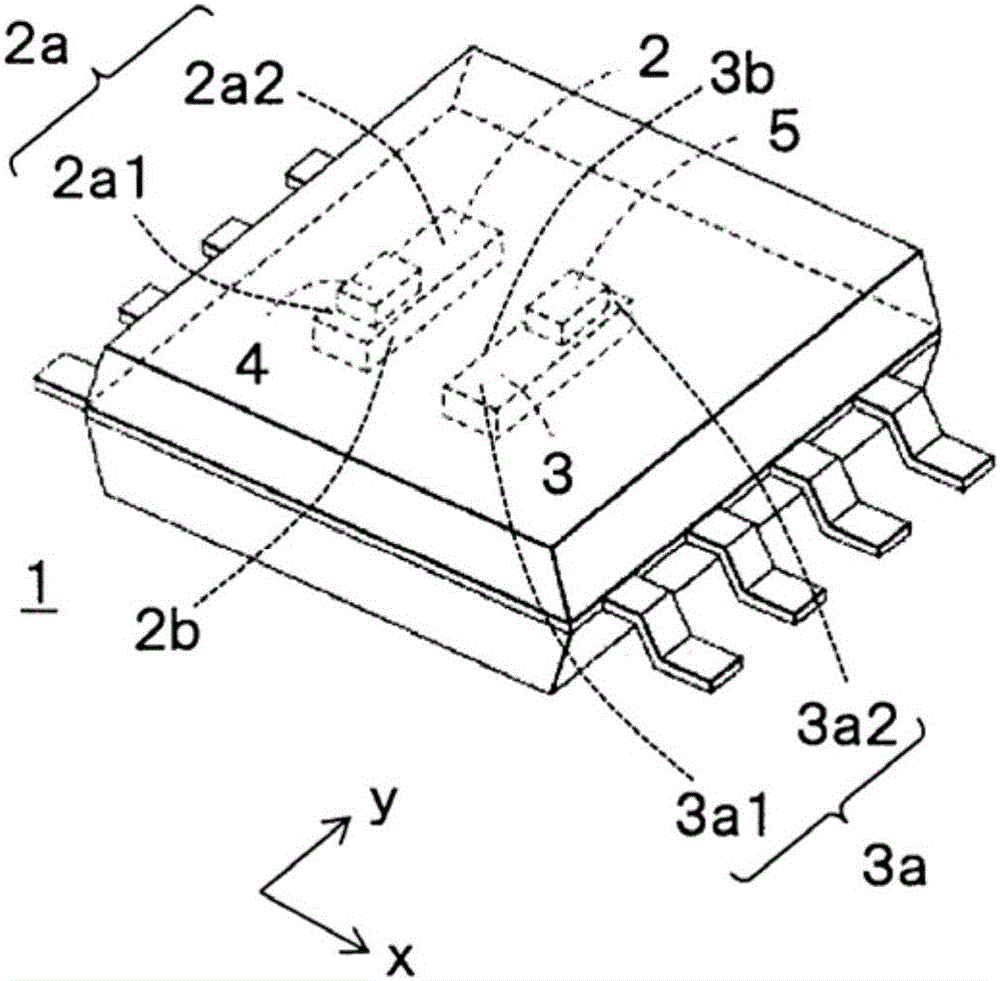
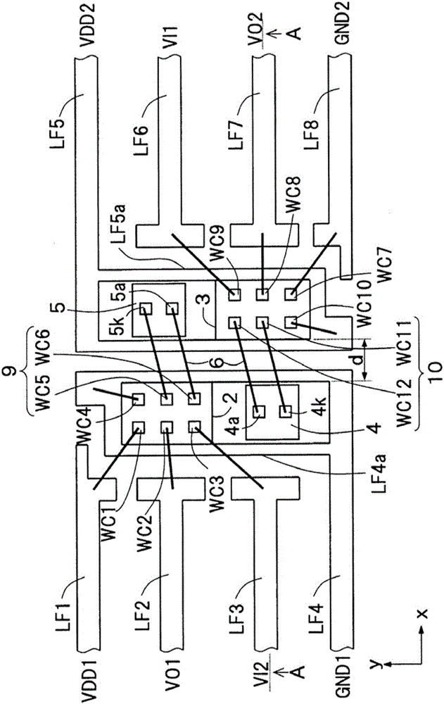
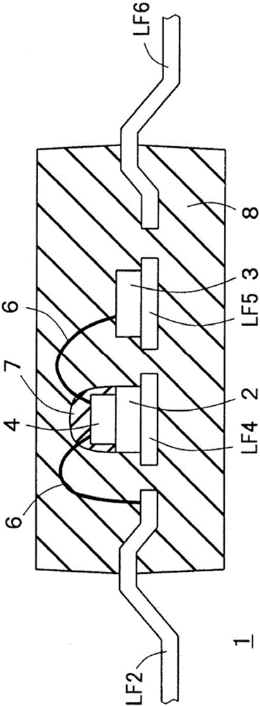
[0022] figure 1 is a perspective view of an optical coupling device 1 according to an embodiment, figure 2 is a layout diagram of the optical coupling device 1 . like figure 1 and figure 2 As shown, the optical coupling device 1 of this embodiment includes: a rectangular first light-receiving chip 2 and a second light-receiving chip 3; a first light-emitting chip 4 arranged on the first light-receiving chip 2; and a second light-emitting chip 4 The chip 5 is disposed on the second light receiving chip 3 .

[0023] The first light-emitting chip 4 and the second light-emitting chip 5 can be semiconductor devices such as LEDs (Light Emission Diode, light-emitting diodes) and other light-emitting elements, and can also be the substrate on which the light-emitting elements are mounted and the surrounding area on which the light-emitting elements are mounted. The subst...


PUM


Abstract

In one embodiment, the invention provides an optical coupling device that can miniaturize packaging and reducing length of joint wire. The optical coupling device includes a first receiving chip having a first region on one end and a second region on another end side. A first emitting chip is disposed on the first region. A second receiving chip has a third region on one end and a fourth region on another end. A second emitting chip is disposed on the fourth region. The first and third regions are adjacent, and the second and fourth regions are adjacent. A first connection portion is disposed on the second region and is electrically connected to the second light emitting chip through a bonding wire. A second connection portion is disposed in the third region and is electrically connected to the first light emitting chip through a bonding wire.

Description

[0001] [Related application] [0002] This application enjoys the priority of the basic application based on Japanese Patent Application No. 2015-153533 (filing date: August 3, 2015). This application incorporates the entire content of the basic application by referring to this basic application. technical field [0003] Embodiments of the present invention relate to an optical coupling device. Background technique [0004] There is known an optical coupling device in which a plurality of optical coupling groups in which a light-emitting element and a light-receiving element are paired are provided in one package. [0005] In such an optical coupling device, so-called crosstalk in which light from a light emitting element of one optical coupling group is received by a light receiving element of another optical coupling group and a signal is erroneously transmitted is likely to occur. Crosstalk can be prevented by increasing the distance between the light-receiving elements...

Claims


Application Information

Patent Timeline
IPC IPC(8): H01L25/16
CPCH01L25/167H01L2924/181H01L2224/05554H01L2224/48091H01L2224/48137H01L2224/48247H01L2224/8592H01L31/167H01L31/02005H01L33/62H01L2924/00014H01L2924/00012H01L25/165
Inventor 钉山裕太斎藤比佐实
Owner KK TOSHIBA
Learn More