Flow distribution apparatus and fuel cell system

A current distribution and electric stack technology, which is applied in the direction of fuel cells, circuits, electrical components, etc., can solve the problem of uneven current distribution of the electric stack body, achieve uniform current distribution, ensure charge and discharge performance, and prolong life

Pending Publication Date: 2017-02-15
TSINGHUA UNIV
View PDF6 Cites 0 Cited by
  • Summary
  • Abstract
  • Description
  • Claims
  • Application Information

AI Technical Summary

Problems solved by technology

[0004] What the present invention aims to solve is the technical problem of uneven current distribution in the stack body in the prior art

Method used


Image

  • Flow distribution apparatus and fuel cell system
  • Flow distribution apparatus and fuel cell system
  • Flow distribution apparatus and fuel cell system

Examples


Embodiment 1

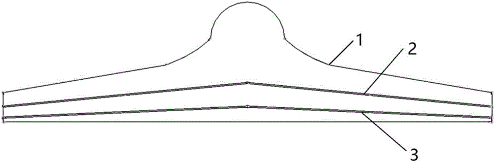
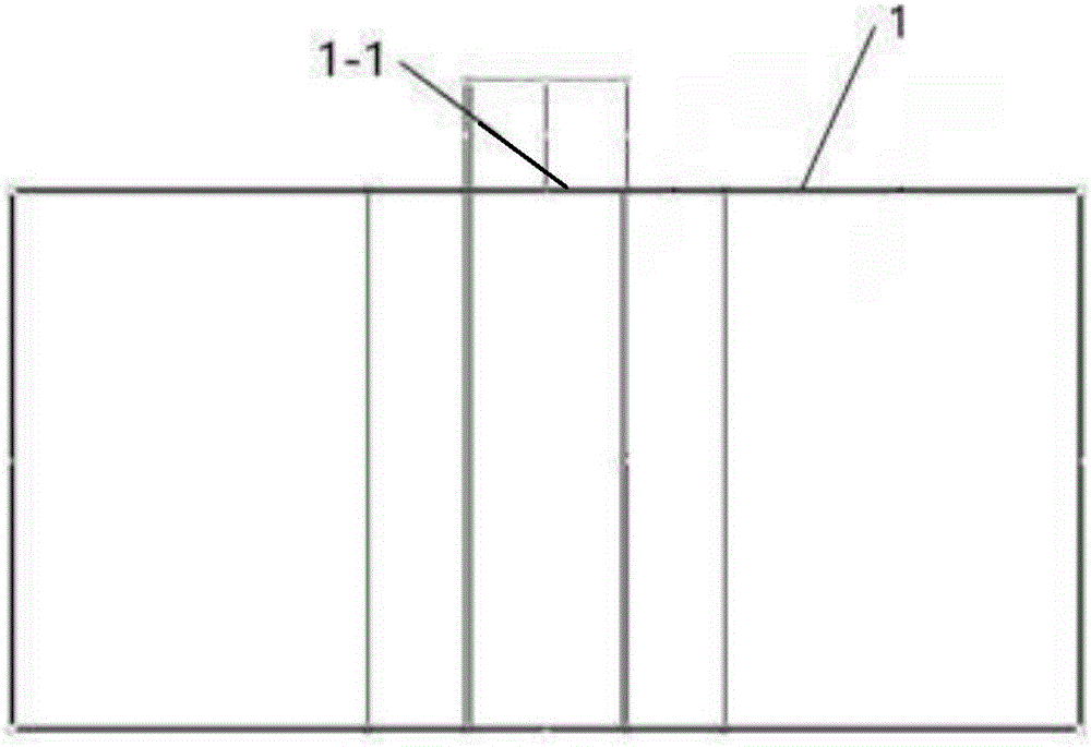
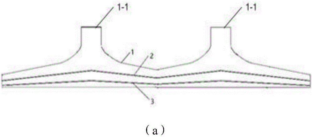
[0028] combine Figure 1 to Figure 3 As shown, the present invention provides a flow distribution device, which includes a top cover 1 and a first baffle plate 2, the top cover 1 has an opening and at least one concave cavity, and the top cover 1 includes a top plate and a shroud around the top plate The first baffle 2 is provided with a plurality of first flow parts 2-1 for the passage of gas, the first baffle 2 is covered at the opening of the top cover 1, and the first baffle 2 is provided with a concave The first bulge corresponding to the cavity, and the first bulge bulges toward the side where the top cover 1 is located, and the top cover 1 is provided with an air inlet 1-1 corresponding to the first bulge, that is, the air inlet 1-1 It can be located on the top plate of the top cover 1 and directly above the first raised portion, or on the enclosure plate of the top cover 1 and directly above the first raised portion. In addition, when the air inlet 1-1 is located on t...

Embodiment 2

[0038] The present invention also provides a fuel cell system, which includes a stack body and the above-mentioned flow distribution device, the intake side cover of the stack body is arranged at the opening of the top cover, and the stack body includes a plurality of bipolar plates, and at least one first through-flow portion is correspondingly provided above each bipolar plate.

[0039] The structure and principle of the flow distribution device in this embodiment are the same as those in Embodiment 1, and will not be repeated in this embodiment. In this embodiment, by setting a flow distribution device, it is ensured that the cathode of each bipolar plate is distributed with air, which promotes the chemical reaction of protons and electrons at the cathode, thereby improving the charging and discharging efficiency of the bipolar plate.

[0040] Further, it also includes the above-mentioned flow distribution device, the exhaust side cover of the stack body is arranged at the ...


PUM


Abstract

The invention relates to the technical field of fuel cells, and provides a flow distribution apparatus and a fuel cell system. The apparatus comprises a top cover and a first baffle plate, the top cover is provided with an opening and at least one recessed cavity, the first baffle plate is provided with a plurality of first flow passing portions used for a gas to pass through, the opening of the top cover is covered with the first baffle plate, the first baffle plate is provided with a first protrusion portion corresponding to the recessed cavity, the first protrusion portion protuberates toward the top cover side, and the top cover is provided with a gas inlet corresponding to the first protrusion portion. The system comprises an electric stack and the flow distribution device, the opening of the top cover is covered with a gas inlet side cover of the electric stack, and the electric stack comprises a plurality of serially connected bipolar plates. The first protuberance portion protuberating toward the top cover side is arranged on the first baffle plate to make the gas flow to two ends from the first protrusion portion under the guiding of an inclined surface of the first baffle plate, so uniform flow distribution is realized, the charge and discharge performances of the electric stack are guaranteed, and the life of the fuel cell is prolonged.

Description

technical field [0001] The invention relates to the technical field of fuel cells, in particular to a flow distribution device and a fuel cell system. Background technique [0002] A fuel cell is an energy converter that converts chemical energy of fuel into electrical energy, the most typical of which is a hydrogen-air proton exchange membrane fuel cell (proton exchange membrane fuel cell, hereinafter referred to as PEMFC). Usually PEMFC is designed in the form of stacks, and each stack is composed of a plurality of single cells stacked in series. Each single cell is composed of anode, cathode and proton exchange membrane. The proton exchange membrane is airtight but can conduct protons. The anode is the place where the hydrogen fuel is oxidized, and the cathode is the place where the oxidant is reduced. Both the cathode and the anode contain accelerating electrodes. Catalyst for chemical reactions. Each single cell is equivalent to a DC power supply when working, its ano...

Claims


Application Information

Patent Timeline
IPC IPC(8): H01M8/0265H01M8/2485
CPCH01M8/0265H01M8/2485Y02E60/50
Inventor 马骁董哲林帅石金
Owner TSINGHUA UNIV
Why Eureka
Try Eureka