
Controlling method for grid-connected photovoltaic system including two-stage voltage inverter

A photovoltaic power generation system and voltage inverter technology, applied in photovoltaic power generation, electrical components, circuit devices, etc., can solve problems such as reducing the utilization rate of power switching devices, difficulty in power flow control, and unbalanced power.

Active Publication Date: 2017-02-15
CHANGZHOU POWER SUPPLY OF JIANGSU ELECTRIC POWER +2
View PDF5 Cites 2 Cited by
  • Summary
  • Abstract
  • Description
  • Claims
  • Application Information

AI Technical Summary

Problems solved by technology

In the actual application process, when the photovoltaic power station is connected to the grid, the corresponding grid system becomes a multi-power system, which will affect the power flow of the system, and the power flow control is difficult; when the inverter outputs a light load, the photovoltaic power station is input to the The harmonic content in the power grid system will increase significantly; when the output side of the inverter fails, the voltage on the AC side of the inverter will decrease, which will reduce the utilization rate of the power switching device, and will generate unbalanced power, affecting photovoltaic power generation. normal operation of the array

Method used


Image

  • Controlling method for grid-connected photovoltaic system including two-stage voltage inverter
  • Controlling method for grid-connected photovoltaic system including two-stage voltage inverter
  • Controlling method for grid-connected photovoltaic system including two-stage voltage inverter

Examples


Embodiment 1

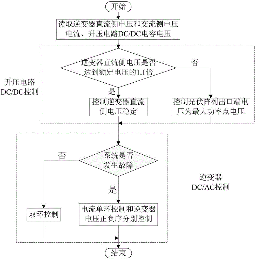
[0025] see figure 1 , the control method of the grid-connected photovoltaic power generation system including the two-stage voltage inverter of the present embodiment includes the following steps:

[0026] ① Collect the DC side voltage U of the inverter through the voltage transformer and current transformer respectively dc and the AC side voltage current U sa , U sb , U sc , I a , I b , I c And the DC / DC input voltage U of the step-up circuit;

[0027] ② According to the data measured in step ①, judge whether the DC side voltage of the inverter reaches 1.1 times the rated voltage; when the inverter DC side voltage reaches 1.1 times the rated voltage, adjust the power switch in the DC / DC boost circuit The device is turned off to control the input DC voltage of the inverter; when the DC side voltage of the inverter does not reach 1.1 times of the rated voltage, the voltage at the outlet end of the photovoltaic array is controlled to the maximum power point voltage, so th...


PUM


Abstract

The invention provides a controlling method for a grid-connected photovoltaic system including a two-stage voltage inverter. The method comprises: step one, a direct-current-side voltage value and alternating-current-side three-phase voltage and current values of an inverter and an input voltage value of a boosted circuit of the inverter are collected; step two, according to practical measurement data, whether the direct-current-side voltage value of the inverter reaches the 1.1 times of a rated voltage is determined, and an input direct-current voltage of the inverter is controlled correspondingly or an outlet voltage of a photovoltaic array is controlled to be a maximum power point voltage; and step three, on the basis of the practical measurement data, whether a threshold determination system is in a normal or faulted state is calculated and determined; if the threshold determination system is in a normal state, dual-loop controlling is carried out on the inverter by ways of voltage outer loop controlling and current inner loop controlling and if the threshold determination system is in a faulted state, positive-sequence and negative-sequence controlling is carried out on the inverter. Under the circumstance that the system works normally, the photovoltaic array can work at a maximum power point; and the direct-current-side voltage of the inverter can be stabilized and a certain reactive power is sent based on the drop degree of the alternating-current-side voltage of the inverter, and thus the grid-side voltage is supported.

Description

technical field [0001] The invention relates to a control method for a grid-connected photovoltaic power generation system, in particular to a control method suitable for a grid-connected photovoltaic power generation system including a two-stage voltage inverter. Background technique [0002] Photovoltaic power generation is divided into two working modes: off-grid and grid-connected. In recent years, photovoltaic power generation and grid-connected technologies have developed rapidly, and solar energy is developing from a "supplementary energy source" to one of the next-generation new "alternative energy sources". Photovoltaic power generation adopts power electronic equipment with extremely fast dynamic process to achieve grid connection, which is completely different from the dynamic characteristics of traditional synchronous machines, so its control method is different from that of traditional synchronous machines. In the actual application process, when the photovolta...

Claims


Application Information

Patent Timeline
Patent Type & Authority Applications(China)
IPC IPC(8): H02J3/38
CPCH02J3/383Y02E10/56
Inventor 董祖晨花丽丹张红洁谢芮芮张志奎
Owner CHANGZHOU POWER SUPPLY OF JIANGSU ELECTRIC POWER
Learn More