
Hand-held multifunctional maintenance power supply device

A multi-functional technology for overhauling power supply, applied in the direction of circuit device, battery circuit device, cooling/ventilation of substation/switchgear, etc. Working conditions and other issues at the job site, to achieve the effect of reducing labor intensity, reducing the time for disconnecting and connecting the power supply, and light weight

Inactive Publication Date: 2017-02-15
STATE GRID CORP OF CHINA +1
View PDF10 Cites 4 Cited by
  • Summary
  • Abstract
  • Description
  • Claims
  • Application Information

AI Technical Summary

Problems solved by technology

[0002] The maintenance power box of the existing substation is usually fixed. During the maintenance and test work in the station, the work team will find that the distance between the maintenance power box and the work site is relatively long, and it is very cumbersome to switch the power line, resulting in a long operation time. Affect work progress and efficiency on site
[0003] Especially when working outside the substation, it is particularly prominent. When working in multiple teams, a large number of temporary power supply panels are required, and frequent power connection work increases the labor intensity of the staff. At the same time, the power cord is lengthened and the external connection The power supply has certain hidden dangers to the safety of on-site construction, and it no longer meets the current conditions of use on the job site
[0004] The maintenance power supply box in the prior art usually only plays the role of a distribution box, and cannot work independently from the AC power supply. This type of maintenance power supply box is disclosed in the patent documents CN103872599B, ​​CN103825350A, CN104734027A, and CN105140788A. When working outside the substation, it still An external AC power supply is required, which is inconvenient to use and has potential safety hazards

Method used


Image

  • Hand-held multifunctional maintenance power supply device
  • Hand-held multifunctional maintenance power supply device
  • Hand-held multifunctional maintenance power supply device

Examples


Embodiment Construction

[0047] It should be noted that, in the case of no conflict, the embodiments in the present application and the features in the embodiments can be combined with each other. The present invention will be described in detail below with reference to the accompanying drawings and examples.

[0048] Figure 1 to Figure 4 Some embodiments according to the invention are shown.

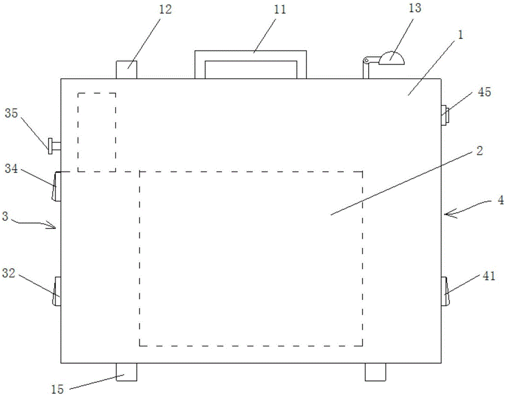
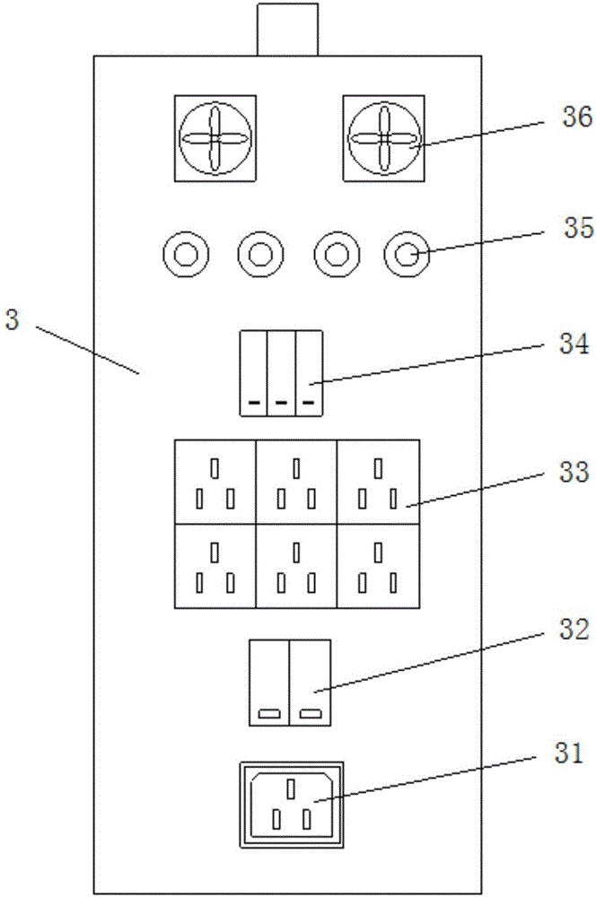
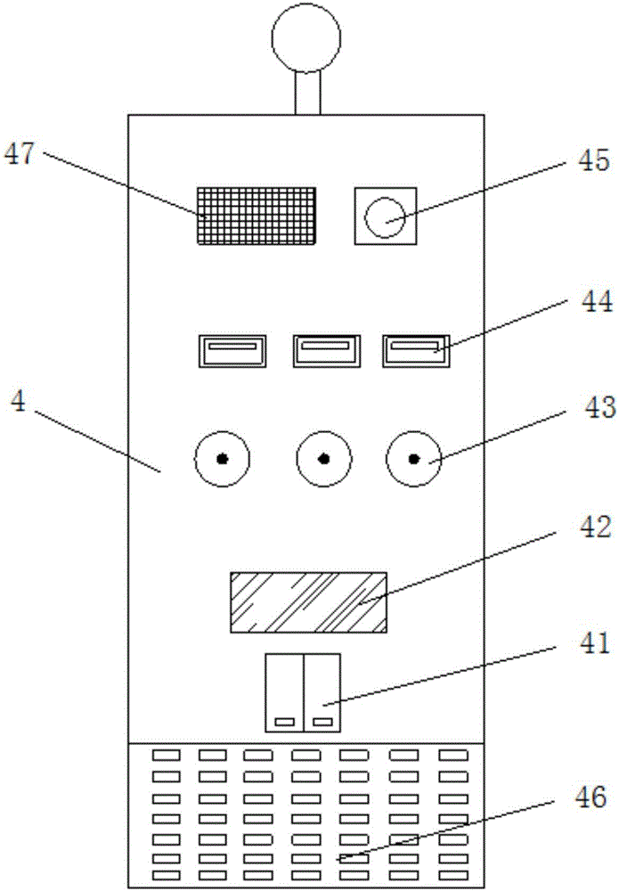
[0049] see Figure 1 to Figure 3 , The portable multi-function maintenance power supply unit includes a box body 1, an electrical combination unit 2 in the box body, an AC panel 3 of the side panel I, and a DC panel 4 of the side panel II. A handle 11, a reset button 12, a folding lighting lamp 13 are arranged on the top of the box body, and a base 14 is arranged on the bottom of the box body.

[0050] AC input socket 31, AC main switch 32, AC output socket 33, AC load switch 34, AC terminal 35 and cooling fan 36 are set on the AC panel of the side panel II of the cabinet; DC load switch 41 and power displa...


PUM


Abstract

The invention discloses a hand-held multifunctional maintenance power supply device comprising a box body and an electrical combination unit. The box body consists of a side plate I alternating-current panel and a side plate II direct-current panel. The electrical combination unit that is used for power distribution for the side plate I alternating-current panel and the side plate II direct-current panel includes a storage battery group, an inversion unit, and a discharging unit. The storage battery group is used for providing a first voltage amplitude output for the inversion unit and providing a second voltage amplitude output for the discharging unit. According to the invention, the box body can be carried conveniently; restriction by an environment is eliminated; and because of the functions, a power demand of the multi-group maintenance power supply at the power production working field can be satisfied.

Description

technical field [0001] The invention relates to a maintenance power supply device, in particular to a portable multifunctional maintenance power supply device used in the field of electric power production. Background technique [0002] The maintenance power box of the existing substation is usually fixed. During the maintenance and test work in the station, the work team will find that the distance between the maintenance power box and the work site is relatively long, and it is very cumbersome to switch the power line, resulting in a long operation time. Affect the work progress and efficiency on site. [0003] Especially when working outside the substation, it is particularly prominent. When working in multiple teams, a large number of temporary power supply panels are required, and frequent power connection work increases the labor intensity of the staff. At the same time, the power cord is lengthened and the external connection The power supply has certain hidden dange...

Claims


Application Information

Patent Timeline
Patent Type & Authority Applications(China)
IPC IPC(8): H02J7/00H02J7/02H02B1/56H02B1/46
CPCH02B1/46H02B1/565H02J7/0063H02J7/02H02J7/027H02J2207/20
Inventor 鲁杰汤建华常先连赵明刘学文吕晓健裴莉杨军伟葛江红刘朝亮何海平李红杰魏永波叶梦云
Owner STATE GRID CORP OF CHINA
Learn More