A charging converter for rail transit

A technology for rail transit and converters, applied in charging stations, current collectors, electric vehicle charging technology, etc., can solve the problems of unconcentrated device layout, poor heat dissipation effect, unscientific air duct design, etc., and achieve compact equipment layout Reasonable, direct air heat exchange, excellent heat dissipation effect

Active Publication Date: 2019-10-15
ZHUZHOU CSR TIMES ELECTRIC CO LTD
View PDF4 Cites 0 Cited by
  • Summary
  • Abstract
  • Description
  • Claims
  • Application Information

AI Technical Summary

Problems solved by technology

Its overall design integration is not good, the overall layout is not compact, it occupies a large area, the rectifier module and chopper module are arranged up and down in the charging area, the flow resistance is large, the heat accumulation is obvious, the heat dissipation effect is not good, and multiple fans are required to be connected in parallel and the noise is large.
At the same time, the layout of the same type of devices in this solution is not centralized, the maintenance and external wiring areas are scattered, and the installation and maintenance operations are inconvenient
[0005] (3) The charging device in the prior art does not fully consider the heat dissipation system design, the air duct design is unscientific, and cannot take away the loss of the main power devices, and at the same time, the flow resistance is large and the noise is large
[0006] (4) The converter of the charging device in the prior art does not fully consider the electromagnetic compatibility of the system, and does not carry out the overall layout according to the level of each voltage level and the sensitivity of device interference (interference); at the same time, the design of the external interface of the converter is not centralized, The connection in the cabinet is complicated, and the installation and maintenance are inconvenient

Method used


Image

  • A charging converter for rail transit
  • A charging converter for rail transit
  • A charging converter for rail transit

Examples


Embodiment Construction

[0028] The present invention will be further described in detail below in conjunction with specific embodiments and drawings.

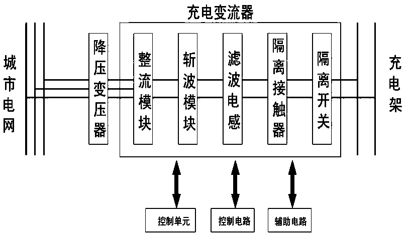
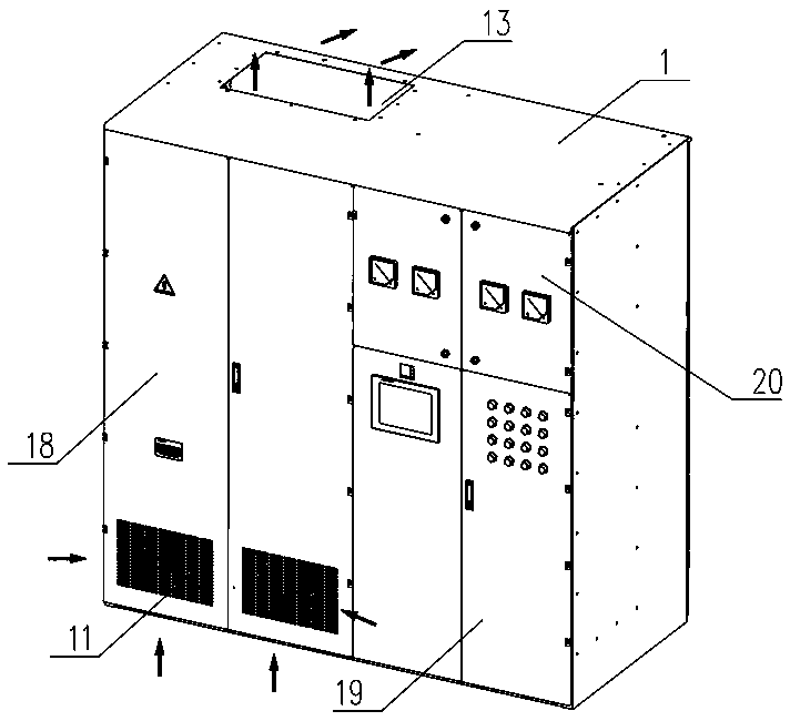
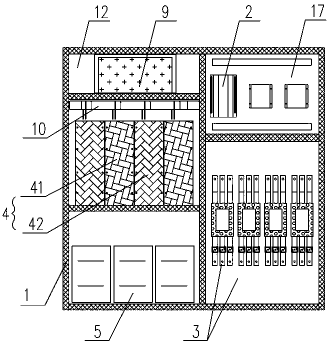
[0029] Such as Figure 1 to Figure 5 As shown, the present invention provides a charging converter for rail transit, including a converter cabinet 1 in which a fan 9, a control circuit module 2, and an input circuit module 3 and a rectifier are electrically connected in turn. Chopper module 4, filter inductor module 5, machine-side contactor module 6, isolating switch module 7, output circuit module 8; fan 9, rectifier chopper module 4, filter inductor module 5 are arranged in cabinet 1 from top to bottom On the left side of the inside, below the cabinet 1 is provided with more than one first vent 11 for cooperating with the fan 9 to form an upper and lower convection heat dissipation air path to dissipate heat from the rectifier chopper module 4 and the filter inductor module 5. The contactor module 6 is arranged behind the rectifier and chopper module ...


PUM


Abstract

The invention discloses a charging converter for rail transit. The charging converter comprises a converter cabinet body, wherein a fan, a control circuit module, an input circuit module, a rectifying and chopping module, a filter inductor module, a machine side contactor module, an isolating switch module and an output circuit module are arranged in the cabinet body; the input circuit module, the rectifying and chopping module, the filter inductor module, the machine side contactor module, the isolating switch module and the output circuit module are electrically connected in sequence; the fan, the rectifying and chopping module and the filter inductor module are sequentially arranged at the left side in the cabinet body from top to bottom; more than one first vent is formed in the lower part of the cabinet body for being matched with the fan to form a cooling wind path for up-and-down convection to cool the rectifying and chopping module and the filter inductor module; the machine side contactor module is arranged at the rear part of the rectifying and chopping module; the control circuit module and the input circuit module are arranged at the right side in the cabinet body from top to bottom; and the isolating switch module and the output circuit module are arranged up and down and arranged at the rear part of the input circuit module in common. The charging converter for rail transit has the advantages of being compact in structure, good in heat dissipation effect, high in maintainability, low in noise and good in electromagnetic compatibility.

Description

Technical field [0001] The present invention mainly relates to the field of rail transit equipment, in particular to a charging converter for rail transit. Background technique [0002] Modern trams include trams and trolleys. Both modern trams have been recognized by many cities in China because of their environmental protection, large passenger capacity, low cost, and good urban environment integration. For the sake of urban beauty and construction cost considerations, the charging device should have low noise, small footprint, and convenient maintenance and use. The current charging converter covers an area of ​​about 4.5 square meters, which puts forward a greater demand for installation space. With the development of technology and the requirements of the owners, the current development direction of the entire charging converter is 2 square meters. This requires a more compact charging converter. The prior art charging converter has the following technical problems: [0003...

Claims


Application Information

Patent Timeline
Patent Type & Authority Patents(China)
IPC IPC(8): H02J7/02H02M1/00H05K7/20H05K5/02B60L53/22
CPCH02J7/022H02M1/00H05K5/0213H05K7/20136Y02T10/70Y02T10/7072Y02T10/72Y02T90/14
Inventor 孙林张祥翁星方董其爱师蒙招王玉斌林文彪殷炯
Owner ZHUZHOU CSR TIMES ELECTRIC CO LTD
Why Eureka
Try Eureka