
Wireless power transmission system and its control method during load switching

A wireless energy transmission and electric energy technology, applied in circuit devices, electrical components, etc., can solve problems such as abnormal state, not a stable constant current source or constant voltage source, system operation, etc., and achieve the effect of suppressing severe fluctuations

Active Publication Date: 2019-03-29
QINGDAO LU YU ENERGY TECH CO LTD
View PDF5 Cites 0 Cited by
  • Summary
  • Abstract
  • Description
  • Claims
  • Application Information

AI Technical Summary

Problems solved by technology

If the output voltage drop at the receiving end is too large, in severe cases, the receiving end system can be in a short-term power-off state, so that the system can work in an uncontrollable abnormal state
In the same way, when the load is switched from heavy load to light load, the temporary detuning of the system will also cause the output voltage of the receiving end to be too high after rectification, which is very easy to burn the voltage regulator circuit of the subsequent stage, or increase the voltage of the subsequent stage circuit. The input voltage stress
To sum up, the receiving end of the wireless power transfer system obtains energy from the electromagnetic field, not a stable constant current source or constant voltage source, and is easily affected by changes in load and the like.

Method used


Image

  • Wireless power transmission system and its control method during load switching
  • Wireless power transmission system and its control method during load switching
  • Wireless power transmission system and its control method during load switching

Examples


Embodiment Construction

[0017] In the following, the present invention will be specifically described through exemplary embodiments. It should be understood, however, that elements, structures and characteristics of one embodiment may be beneficially incorporated in other embodiments without further recitation.

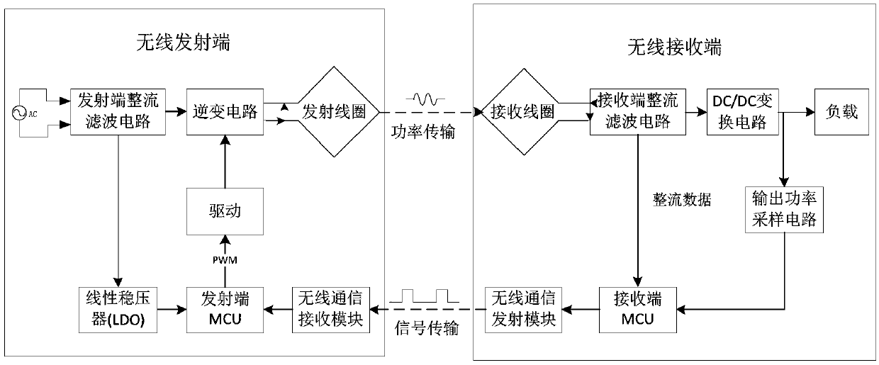
[0018] see figure 1 , is a schematic diagram of the wireless power transmission system of the present invention, such as figure 1 As shown, the wireless power transmission system of the present invention includes a wireless transmitter connected to the power grid, and a wireless receiver capable of receiving power from the wireless transmitter. The wireless communication receiving module; the external load of the wireless receiving end, including the receiving coil that can receive the transmitted electric energy in the transmitting coil, and the wireless communication transmitting module that can convert the output electric energy of the receiving coil into a communication signal and trans...


PUM


Abstract

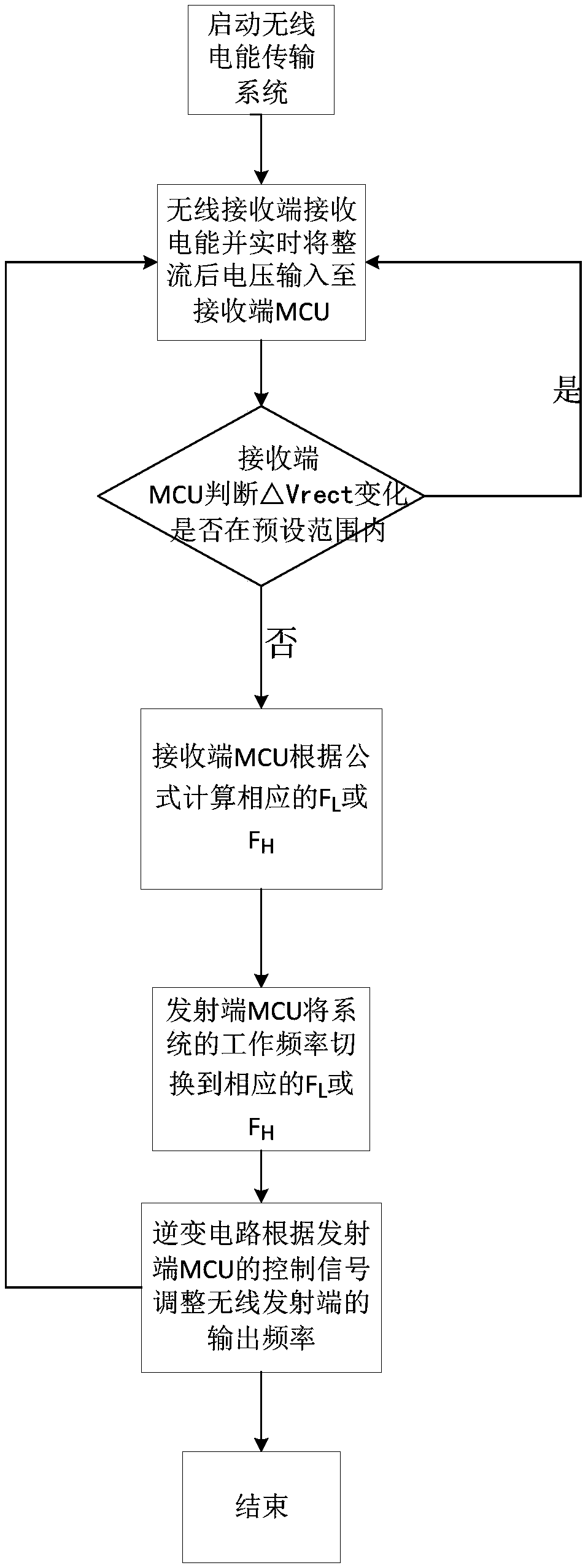
The present invention proposes a wireless energy transmission system and a control method for load switching thereof. In the invention, the MCU at the receiving end collects the output voltage of the rectifying and filtering circuit at the receiving end in real time, and judges in real time whether the load is switched and whether the load is switched based on the amplitude of the output voltage change. According to this, the operating frequency of the system is adjusted to quickly jump to a new resonant operating frequency, so that the system can quickly return to the new resonant state, thereby suppressing the sudden change of the voltage after rectification, so as to quickly reach the re-stabilized state of the system. The invention can effectively prevent the excessive fluctuation of the rectified voltage caused by the load change of the wireless receiving end, and improves the working stability of the wireless energy transmission system.

Description

technical field [0001] The invention belongs to the field of wireless power transmission, and in particular relates to a load switching control method in a wireless power transmission system. Background technique [0002] In recent years, wireless charging technology has developed rapidly. Because of its non-contact, wire-free connection, and convenient operation, it has attracted much attention, and various wireless charging products have also come out one after another. As its wireless charging technology matures and its application fields become more and more extensive, power improvement and better user experience are becoming more and more important. [0003] The existing wireless charging system, as a whole, includes two parts: the wireless energy transmitter and the wireless energy receiver, and the wireless energy transmitter and the wireless energy receiver transmit energy through a magnetic field, and there is no wire connection between the two. To obtain the statu...

Claims


Application Information

Patent Timeline
Patent Type & Authority Patents(China)
IPC IPC(8): H02J50/12
CPCH02J5/005
Inventor 李聃袁浩
Owner QINGDAO LU YU ENERGY TECH CO LTD
Learn More