Inverter power compensation method based on droop control

A power compensation and inverter technology, applied in the direction of reducing/preventing power oscillation, current collectors, circuit monitoring/indicating, etc., can solve the problems of unfavorable load power grid scheduling, inapplicable energy storage battery supplementary power and energy storage, etc. Achieve the effect of preventing generator power overload from damaging equipment, suppressing violent fluctuations, and improving stability

Pending Publication Date: 2022-06-07
HEBEI UNIV OF TECH +1
View PDF1 Cites 0 Cited by
  • Summary
  • Abstract
  • Description
  • Claims
  • Application Information

AI Technical Summary

Problems solved by technology

[0003] In the patent of CN 106099983 A, an improved adaptive droop control method for inverters in low-voltage microgrids, the method introduces virtual complex impedance to make the equivalent output impedance of parallel inverters inductive. The voltage drop caused by the virtual complex impedance is improved by adaptive droop control, and the load sharing of parallel inverters is realized. However, this method is not suitable for energy storage batteries and energy storage. Points are not conducive to grid dispatching

Method used


Image

  • Inverter power compensation method based on droop control
  • Inverter power compensation method based on droop control
  • Inverter power compensation method based on droop control

Examples


Embodiment 1

[0177] In a preferred embodiment, a 30KW inverter is selected for verification, the inverter having two distributed generation ports, an energy storage charging and discharging port, an inverter output port, the inverter output port is a three-phase four-wire port, a distributed generation port is a three-phase universal power port, can be connected to 100-500V co-frequency power supply, distributed power generation port two is a standby port, and distributed generation port one has the same structure and function.

[0178] The distributed generation port one is connected to a three-phase power frequency generator with adjustable output voltage, the energy storage charging and discharging port is connected to the energy storage battery with a rated voltage of 535V, the inverter output port is connected to a three-wire four-wire electronic load connection, and the real-time load power change is achieved by adjusting the electronic load, thereby verifying the inverter power compensa...

Embodiment 2

[0204] The operating conditions are similar to Example 1 and will not be repeated, the difference is that,

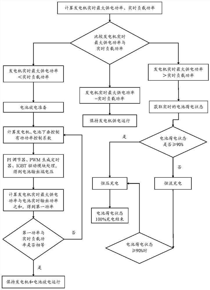
[0205] T 2 At the moment, the generator speed n = 3300r / min, as followed Figure 1 The flowchart shown includes the following steps:

[0206] S1: Calculate the generator real-time maximum power supply power, real-time load power;

[0207]According to Table 1, it can be seen that when the generator speed is 3300r / min, the conversion coefficient N between the rms value of the generator power and the rms value of the generator terminal voltage is 0.045, and the conversion coefficient Y between the rms value of the generator end voltage and the generator speed is 40, and the rms value of the generator end voltage is 150V after calculation, and the maximum power supply power of the generator in real time is P gent_max 6.00KW.

[0208] By the electronic load can be known, the real-time load power P load 2.7KW.

[0209] S2: The generator real-time maximum power supply power P gent_...

Embodiment 3

[0222] The same as Example 2 will not be repeated, the difference is that,

[0223] S21: The current real-time battery charge status (SOC) is obtained through the battery management system (BMS) of 91%, indicating that the remaining available power of the current battery accounts for 91% of the total capacity;

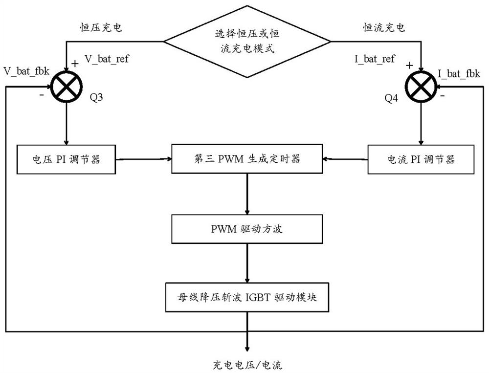
[0224]S22: In order to fully ensure the charging efficiency and charging safety, the present application to the battery nuclear power state 90% as the boundary, distinguish between constant current charging and constant voltage charging mode, since the current battery charge state > 90%, into the battery constant voltage charging mode, the battery for constant voltage charging, comprising the following steps:

[0225] S221: Obtain the battery allowable charging voltage corresponding to the battery state of charge, comprising the following steps:

[0226] S2211: The reference voltage of constant voltage charging corresponding to the current battery charge state is obtained ...


PUM


Abstract

The invention provides an inverter power compensation method based on droop control, and the method comprises the steps: obtaining the real-time maximum power supply power and the real-time load power of a generator, and modifying the droop control active power control coefficient of the generator in real time when the real-time maximum power supply power of the generator is smaller than the real-time load power; and determining a battery droop control active power control coefficient according to the generator droop control active power control coefficient, and ensuring full utilization of the generator power and reasonable distribution of the battery discharge power compensation power by using the adaptive characteristic of the inverter droop controller, thereby realizing the purpose that the battery droop control active power control coefficient is fully utilized under the condition that the generator power is insufficient. The function of automatically compensating the power according to the real-time load power demand is realized, and the change demand of the load power is met in time, so that the violent fluctuation of the bus voltage at the input end and the output end voltage of the inverter caused by the increase of the load power is effectively inhibited, the equipment damage caused by power overload of the generator is prevented, and the stability of the operating voltage of the inverter is improved.

Description

Technical field [0001] The present invention relates to the field of microgrid control technology, particularly to an inverter power compensation method based on sag control. Background [0002] With the continuous advancement of various new energy power generation technologies, power generation methods have been greatly enriched, such as photovoltaic power generation, wind power generation, thermal power generation, etc., but the development of power generation technology has not solved the problem of unbalanced power supply and waste of power in the power system. With the continuous development of electric vehicle technology, battery technology has been greatly developed, from cost, charge and discharge performance to safety have been further improved, thanks to the progress of battery technology, how to apply the energy storage effect of the battery to the power system, and the effective combination of the power system to achieve energy balance and full use has become a hot sp...

Claims


Application Information

Patent Timeline
Patent Type & Authority Applications(China)
IPC IPC(8): H02J3/38H02J3/48H02J3/32H02J3/24H02J7/00
CPCH02J3/38H02J3/48H02J3/32H02J3/24H02J7/0048H02J7/0029H02J7/00712Y02E70/30
Inventor 李练兵宋清翔康伟伟李峰杨海跃高丽娟郗兵
Owner HEBEI UNIV OF TECH
Why Eureka
Try Eureka