
Water-cooled heat dissipation type pressure-resistant electronic cabin

A technology of water cooling and heat dissipation, electronic cabin, applied in cooling/ventilation/heating transformation, underwater ships, underwater operation equipment, etc., can solve the problems of not considering the heat dissipation of electrical components, small effective installation area, and not being effectively solved. , to achieve the effect of extending sustainable working time, improving heat dissipation efficiency, and improving space utilization

Active Publication Date: 2017-02-15
JIANGSU UNIV OF SCI & TECH
View PDF5 Cites 8 Cited by
  • Summary
  • Abstract
  • Description
  • Claims
  • Application Information

AI Technical Summary

Problems solved by technology

A few patents have designed a detachable electronic equipment bracket, but its structure is too complicated, and the loading and unloading process is relatively cumbersome
The electronic pressure chamber invented in Chinese Patent No. ZL200610134453.9 has a movable electronic docking frame, but the effective installation area is small, the number of equipment that can be carried is limited, and the heat dissipation of electrical components is not considered
The above problems have not been effectively resolved

Method used


Image

  • Water-cooled heat dissipation type pressure-resistant electronic cabin
  • Water-cooled heat dissipation type pressure-resistant electronic cabin
  • Water-cooled heat dissipation type pressure-resistant electronic cabin

Examples


Embodiment Construction

[0027] The present invention will be further described below in conjunction with the accompanying drawings.

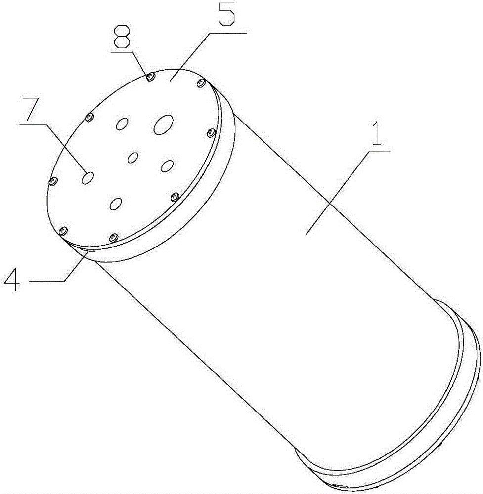
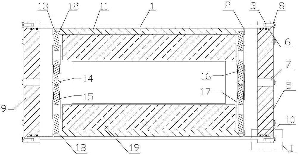
[0028] Such as Figure 1 to Figure 6 As shown, the pressure tank shell among the present invention comprises a cylindrical main cabin body 1, a cylindrical front end cover 5 and a cylindrical rear end cover 9. Flanges are left at both ends of the main cabin body 1, and eight threaded holes 3 symmetrical to the center of the axis are provided on the end surface of the flange, and two dismounting grooves 4 symmetrical to the center of the axis are provided on the end surface of the flange.

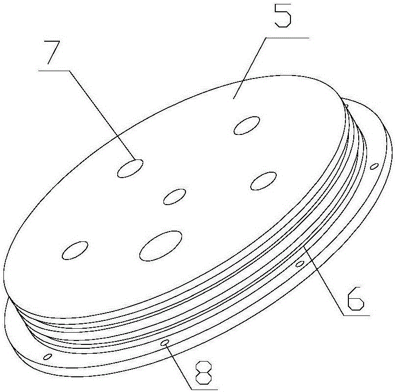
[0029] Such as figure 2 As shown, the front end cover 5 is a second-order cylindrical structure, and the outer cylindrical end surface is provided with eight circular positioning holes 8 corresponding to the main cabin body 1, and the inner cylindrical end surface is provided with a number of connectors for installing watertight cable connectors. The socket 7 has two annular seali...


PUM

PropertyMeasurementUnit
Angleaaaaaaaaaa

Abstract

The invention discloses a water-cooled heat dissipation type pressure-resistant electronic cabin which comprises a main cabin body. A front end cover and a rear end cover are respectively arranged on both ends of the main cabin body. The main cabin body is sealed into a cavity by the front end cover and the rear end cover. A heat dissipation device is arranged in the cavity. The heat dissipation device comprises four heat sinks which are supported by cross-shaped telescopic brackets on both ends and are arranged on the inner wall of the cavity through the cross-shaped telescopic brackets. The heat sinks are arranged on electrical components. According to the water-cooled heat dissipation type pressure-resistant electronic cabin, the pressure-resistant cabin casing and the internal electrical device are respectively two separate systems, and can be completely separated; the convenience of assembling and debugging is improved; the electrical device is arranged on a separate heat dissipation bracket; the heat dissipation bracket can transfer heat of the electrical components to the wall of the pressure-resistant cabin and water outside the cabin; heat dissipation of the electrical device in the cabin body is realized; and in addition, the support effect of the heat dissipation bracket on the cabin wall enhances the pressure-resistant ability of the pressure-resistant cabin casing and improves the reliability of the whole system.

Description

technical field [0001] The invention relates to a water-cooled and heat-dissipating pressure-resistant electronic cabin, which belongs to the field of underwater engineering. Background technique [0002] The electrical equipment in deep-water submersibles usually needs to work under anhydrous conditions, so they must be placed in a watertight airtight cabin, and the cabin must have sufficient pressure resistance to remain unchanged under external water pressure. Thereby protecting the internal equipment. In order to ensure the compressive strength, the underwater pressure-resistant housing is generally designed in a cylindrical or spherical shape, but compared with a square cabin, its internal curved surface makes it difficult to install and debug electrical components, and the space utilization rate will be greatly reduced. In addition, some electrical components generate high heat during operation, and the airtight pressure-resistant housing and uneven internal surface a...

Claims


Application Information

Patent Timeline
IPC IPC(8): H05K7/20B63G8/00
CPCB63G8/00H05K7/2039
Inventor 卞子玮王志东凌宏杰邓超侯明君窦朋彭冲
Owner JIANGSU UNIV OF SCI & TECH
Learn More