One-piece multi-station hemming mold
A multi-station, integrated technology, applied in the direction of forming tools, manufacturing tools, metal processing equipment, etc., can solve the problems of single use and reduction, and achieve the effects of reduced spare parts, high bending precision and simple structure
- Summary
- Abstract
- Description
- Claims
- Application Information
AI Technical Summary
Problems solved by technology
Method used
Image
Examples
Embodiment 1
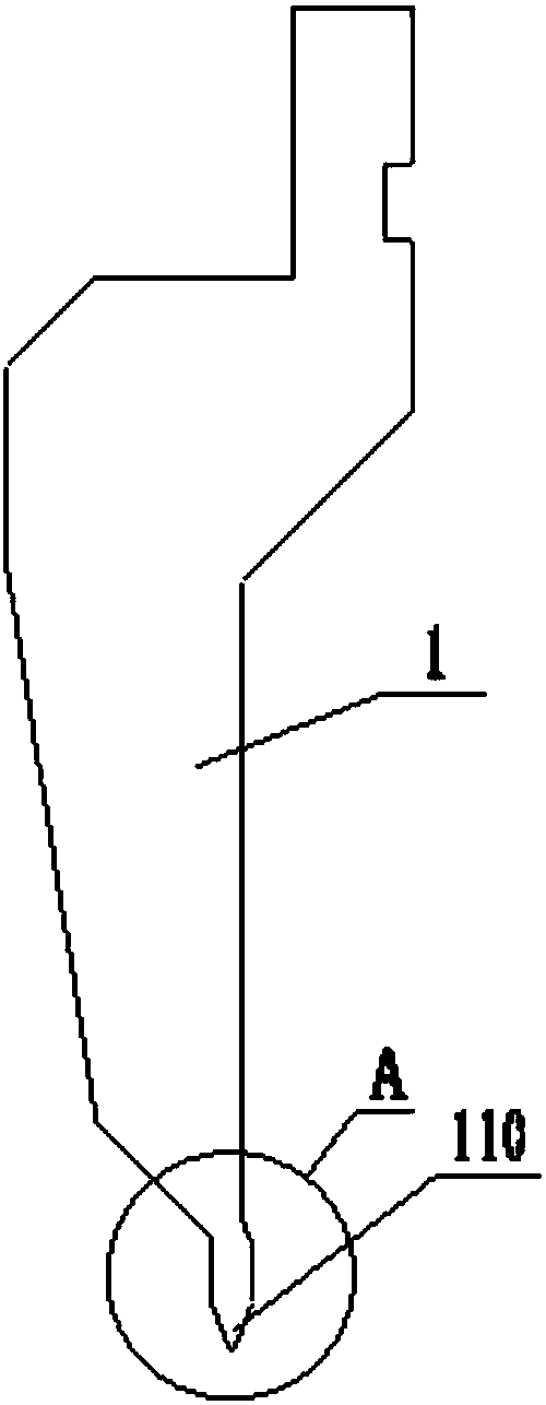
[0061] Such as figure 2 , Figure 4 , Figure 5 , Image 6 , Figure 7 with Figure 8 As shown, the integrated multi-station flanging mold of the present embodiment includes an upper mold 1, a middle mold 2 and a lower mold 3; wherein, the middle mold 2 includes a middle mold base 210 and a die 220, and the left side of the middle mold base 210 An L-shaped notch is provided on the side, and the die 220 is placed in the L-shaped notch, and is detachably connected with the middle mold base 210 by bolts. It should be noted that the middle mold base 210 and the concave mold 220 can be of an integrated structure, while this embodiment adopts a detachable connection structure, which is convenient for processing and saves materials, and is also convenient for maintenance, and will be scrapped due to wear and tear after long-term use Finally, only one of them needs to be replaced, reducing maintenance costs. The upper surface of the die 220 is provided with a V-shaped groove 22...
Embodiment 2
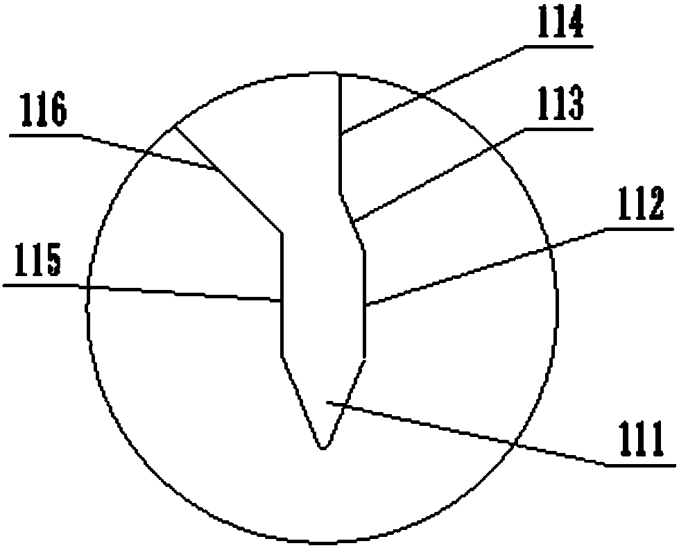
[0067] The integrated multi-station hemming die of this embodiment is further improved on the basis of Embodiment 1 to meet the bending requirements of special Z-shaped workpieces. figure 2 with image 3, in the working part 110 of the upper mold 1, the right side of the V-shaped die head 111 is sequentially connected to the first side 112, the second side 113 and the third side 114, the first side 112 and the third side 114 are vertical planes, the second The two sides 113 are inclined planes, and the angle between the first side 112 and the second side 113 is greater than 180°; the left side of the V-shaped die head 111 is connected to the fourth side 115 and the fifth side 116 in turn, and the fourth side 115 is a vertical plane , the angle between the fourth side 115 and the fifth side 116 is greater than 90° but less than 180°. This kind of structural design can avoid the upturning of both sides during bending when bending special Z-shaped workpieces, so that the proces...
Embodiment 3
[0069] The present embodiment provides the bending method of special Z-shaped workpiece, and the special Z-shaped workpiece shape of bending is as follows figure 1 As shown, the thickness of the workpiece is 1.5mm, and it includes the first flat section A, the second flat section B, the third flat section C and the fourth flat section D connected in sequence, wherein the first flat section A and the second flat section The included angle between the flat sections B and the included angle between the second flat section B and the third flat section C are both 90°, and the included angle between the third flat section C and the fourth flat section D is 0°, That is to say, the fourth flat section D is in close contact with the third flat section C. The integrated multi-station flanging mold of embodiment 2 is adopted for processing, and the specific operation steps are as follows:
[0070] ① Mold installation preparation
[0071] According to the mechanism of embodiment 2, the ...
PUM
 Abstract
Description
Claims
Application Information
 - R&D
- Intellectual Property
- Life Sciences
- Materials
- Tech Scout
- Unparalleled Data Quality
- Higher Quality Content
- 60% Fewer Hallucinations
Browse by: Latest US Patents, China's latest patents, Technical Efficacy Thesaurus, Application Domain, Technology Topic, Popular Technical Reports.
© 2025 PatSnap. All rights reserved.Legal|Privacy policy|Modern Slavery Act Transparency Statement|Sitemap|About US| Contact US: help@patsnap.com


