Device capable of improving machining quality of clutch coil shell

A processing quality and clutch technology, applied in metal processing equipment, metal processing machinery parts, manufacturing tools, etc., can solve problems such as easily scratched product surfaces, hidden safety hazards, and affecting processing quality, so as to improve turning efficiency and improve turning efficiency. Good quality and product processing quality

Inactive Publication Date: 2017-02-22
浙江瑞虹机电股份有限公司
View PDF9 Cites 3 Cited by
  • Summary
  • Abstract
  • Description
  • Claims
  • Application Information

AI Technical Summary

Problems solved by technology

[0002] A few days ago, the clutch coil housing of the automobile air conditioner is formed by integral stamping of a circular raw material steel plate. One side of the machine is in the shape of a ring, and the edges of the inner ring and outer ring need to be turned by two turning tools. In the actual processing process, the waste generated after turning falls directly to the receiving trough directly under the main shaft. Inside, one side of the receiving trough is transitionally connected to the inclined output channel. When the waste in the receiving trough is full, the operator will push it into the output channel through the lever, and the waste will slide out of the equipment along the output channel. Scattering takes up a lot of space and is scattered around the equipment. On the one hand, there are potential safety hazards, and on the other hand, it is not conducive to waste recycling
In addition, as we all know, during turning, waste materials are usually stuck to the turning tool. If it is not cleared in time, it is easy to scratch the surface of the product when processing the next product, which will affect the processing quality. Up and down, but there are some problems. The lever is generally a rigid part, and its rigid contact with the turning tool is easy to damage the turning tool. At the same time, workers need to always observe whether there is waste on the turning tool. The labor intensity is high and the work efficiency is low.

Method used


Image

  • Device capable of improving machining quality of clutch coil shell
  • Device capable of improving machining quality of clutch coil shell
  • Device capable of improving machining quality of clutch coil shell

Examples


Embodiment

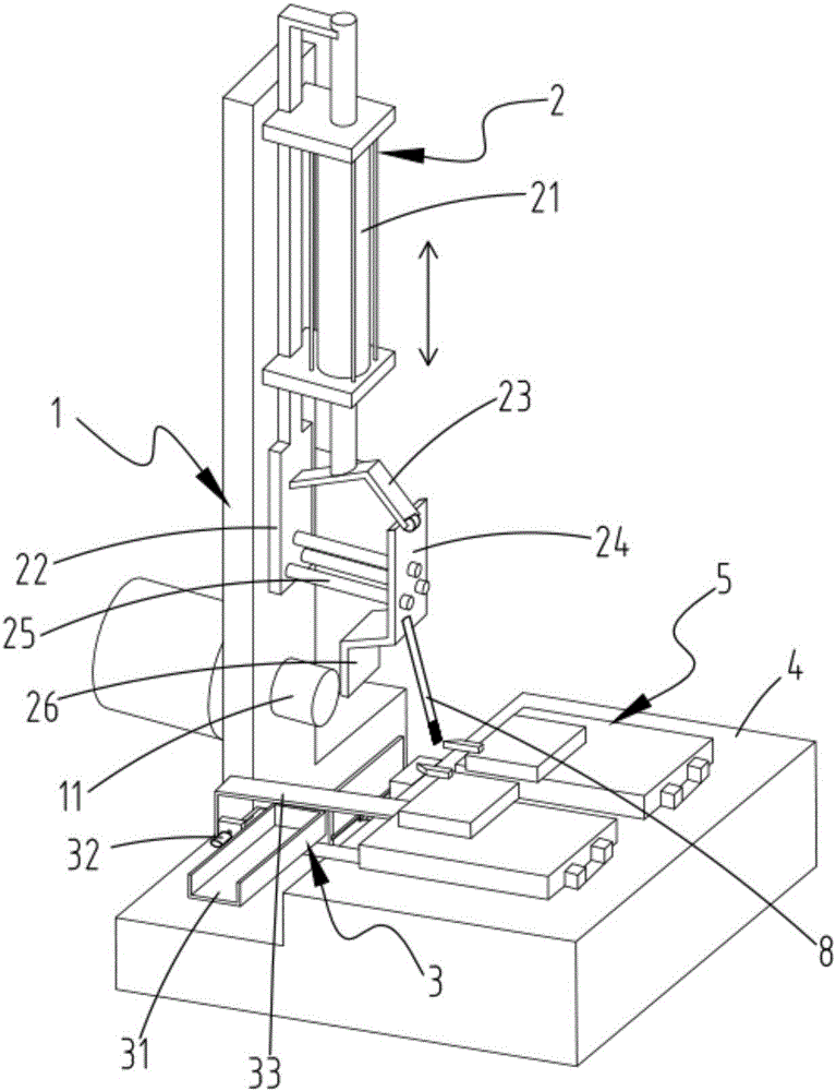
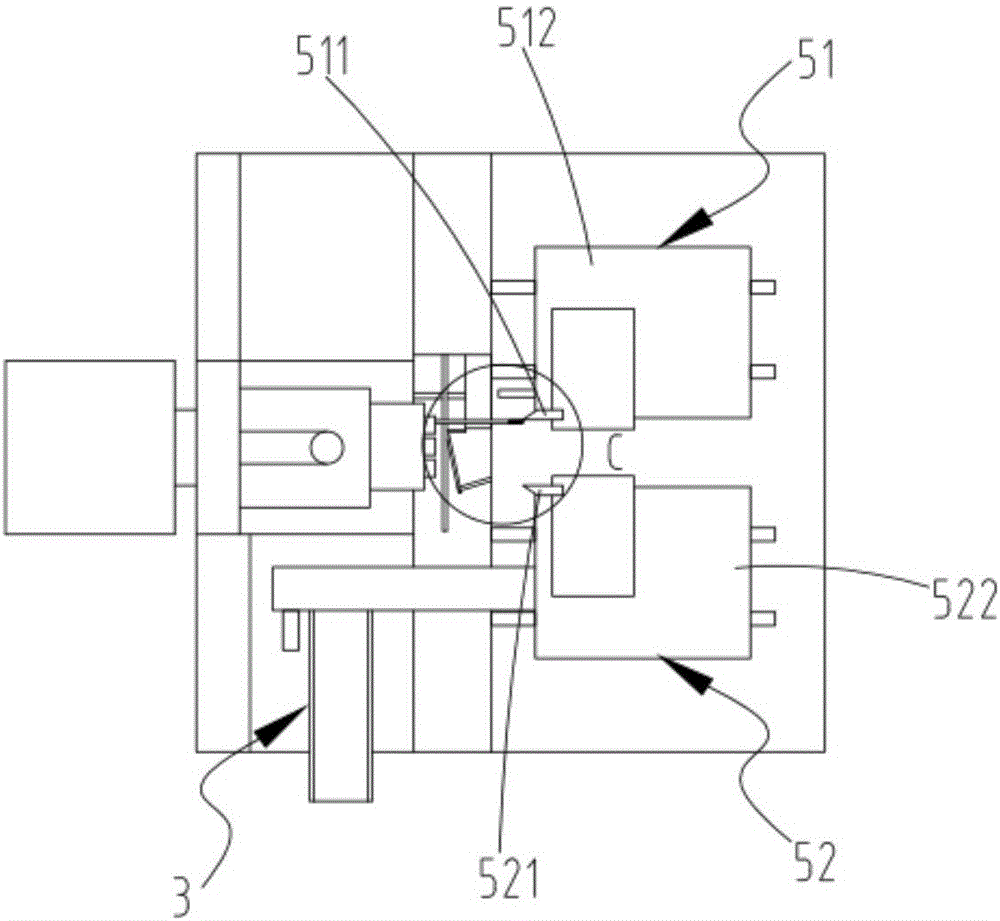
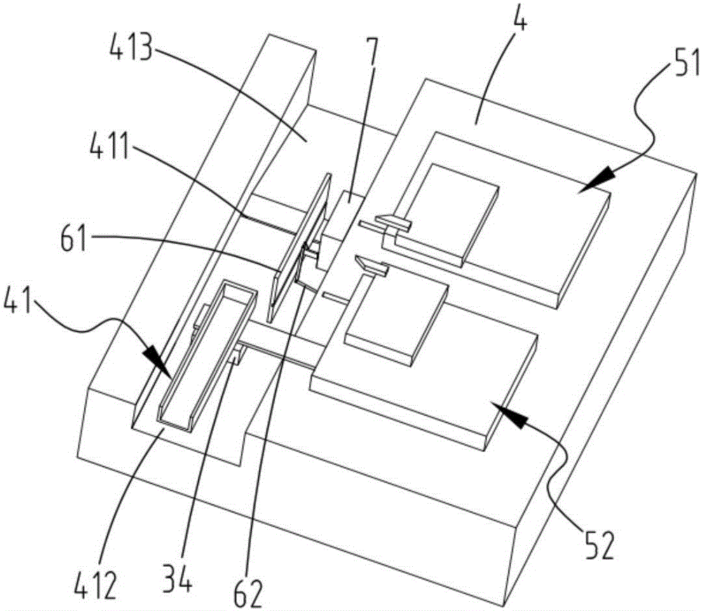
[0028] Such as figure 1 As shown, the present invention provides a kind of equipment for improving the processing quality of the clutch coil casing, including a frame 1, a main shaft 11 installed on the frame 1 for driving the rotation of the coil casing, and used for sending the coil casing to the main shaft The feeding mechanism 2 on 11, the blanking mechanism 3 for the output of the coil casing after processing, and the turning device 5 installed on the workbench 4, and the workbench 4 is located between the main shaft 11 and the turning device 5. Waste output channel 41, such as figure 2 with image 3 As shown, the turning device 5 includes a first feed module 51 and a second feed module 52 that are relatively parallel and slide on the workbench 4. The first feed module 51 includes a first driving device and a front end surface installation. There is a first mounting seat 512 of the first turning tool 511; the front ends of the first feeding module 51 and the second fee...


PUM


Abstract

The invention relates to a clutch coil shell turning waste collection device. The device comprises a rack, a spindle, a feeding mechanism, a discharging mechanism and a turning device; a waste output channel is formed in a work table, the turning device comprises a first feeding module and a second feeding module which are arranged on the work table in a relatively-parallel and sliding manner, the front end of the first feeding module and the front end of the second feeding module are provided with an extrusion mechanism used for shaping wastes in a waste output channel; the extrusion mechanism comprises a striker plate and a connecting rod mechanism; the front end face of the first feeding module is provided with an extrusion plate in a protruding manner, and a waste extrusion area is formed between the extrusion plate and the striker plate; the feeding mechanism inclines downwards to be provided with a material shifting rod, the feeding mechanism moves downwards, and the tail end of the material shifting rod makes contact with the end of a first turning tool. The material shifting rod is used for shifting wastes remaining on the turning tool after turning, the waste extrusion mechanism and the discharging mechanism are combined, in-batch recycling of wastes is achieved, the waste occupied space is reduced, and the recycling cost is reduced.

Description

technical field [0001] The invention relates to the technical field of waste material collection, in particular to a device for improving the processing quality of a clutch coil housing. Background technique [0002] A few days ago, the clutch coil housing of the automobile air conditioner is formed by integral stamping of a circular raw material steel plate. One side of the machine is in the shape of a ring, and the edges of the inner ring and outer ring need to be turned by two turning tools. In the actual processing process, the waste generated after turning falls directly to the receiving trough directly under the main shaft. Inside, one side of the receiving trough is transitionally connected to the inclined output channel. When the waste in the receiving trough is full, the operator will push it into the output channel through the lever, and the waste will slide out of the equipment along the output channel. Scattering takes up a lot of space and is scattered around t...

Claims


Application Information

Patent Timeline
IPC IPC(8): B23Q11/00B30B9/32
CPCB23Q11/0042B30B9/32
Inventor 李明勇谢建勇欧央伟戴胜杰
Owner 浙江瑞虹机电股份有限公司
Why Eureka
Try Eureka