Arrangement structure of double-pull-rod steering system of passenger vehicle
A technology of steering system and layout structure, which is applied to steering mechanism, steering rod, vehicle components, etc., can solve the problems of uneven steering force, unfavorable vehicle layout, and unfavorable steering control, so as to achieve uniform steering force and facilitate steering control. , the effect of easy to turn back to positive
- Summary
- Abstract
- Description
- Claims
- Application Information
AI Technical Summary
Problems solved by technology
Method used
Image
Examples
Embodiment 1
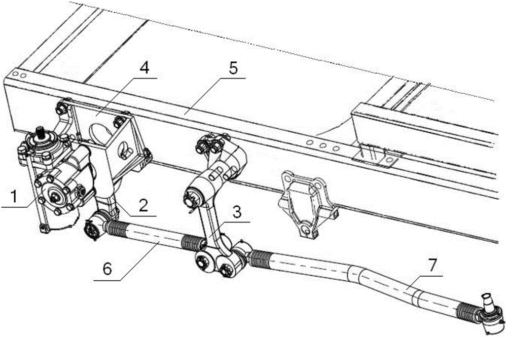
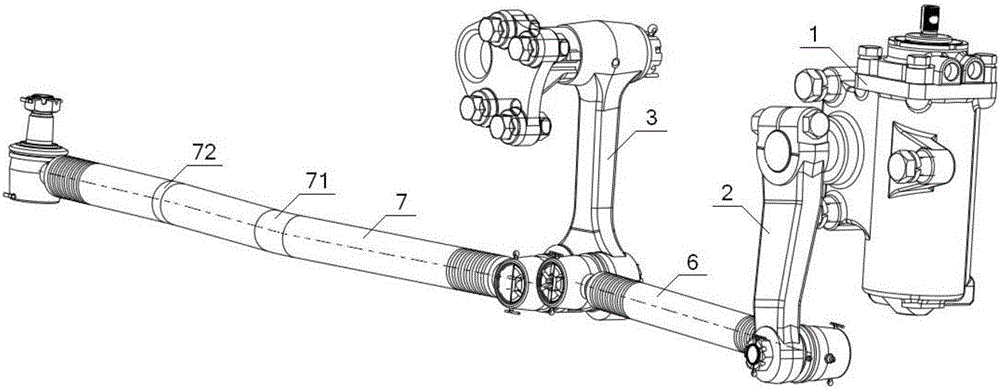
[0057] see figure 1 , figure 2 , Figure 9 , an arrangement structure of a passenger car double-tie rod steering system, comprising a steering gear 1, a steering drop arm 2, and an intermediate drop arm assembly 3, wherein the intermediate drop arm assembly 3 includes an intermediate drop arm bracket 31, a drop arm support shaft 32, The middle drop arm 33, the steering gear 1 is fixed on the left longitudinal beam 5 of the vehicle frame through the steering gear bracket 4, and the middle drop arm 33 includes a drop arm body 331 and a drop arm rotating end 332 connected to the vertical arm body 331 and its two ends respectively. The arm taper hole end 333, the vertical arm rotating end 332 is fixed on the middle vertical arm bracket 31 through the vertical arm support shaft 32, the middle vertical arm bracket 31 is fixed on the left longitudinal beam 5 of the vehicle frame, the vertical arm taper hole end 333 is provided with a No. 1 taper hole 335 at a position close to the...
Embodiment 2
[0059] Basic content is the same as embodiment 1, the difference is:
[0060] see image 3 , the first centerline 61 of the first straight rod 6 is coaxial with the second centerline 73 of the second straight rod 7;
[0061] see figure 1 , Figure 4 , the direction of the No. 1 tapered hole 335 and the No. 2 tapered hole 336 can be in the same direction or in different directions. The ball joint assemblies at both ends of the first straight tie rod 6 can be in the same direction or in different directions. The second straight tie rod 7 The direction of the ball head at the front end can be arranged according to the relative positional relationship of the straight tie rod, the tire, and the leaf spring front bracket.
Embodiment 3
[0063] Basic content is the same as embodiment 1, the difference is:
[0064] see figure 1 , figure 2 , the length of the first straight rod 6 is 400 mm to 600 mm, the length of the second straight rod 7 is 900 mm to 1200 mm; the second straight rod 7 is provided with a bending angle 71 and two No. bending angle 72.
PUM
| Property | Measurement | Unit |
|---|---|---|
| Length | aaaaa | aaaaa |
| Length | aaaaa | aaaaa |
Abstract
Description
Claims
Application Information
 - R&D
- Intellectual Property
- Life Sciences
- Materials
- Tech Scout
- Unparalleled Data Quality
- Higher Quality Content
- 60% Fewer Hallucinations
Browse by: Latest US Patents, China's latest patents, Technical Efficacy Thesaurus, Application Domain, Technology Topic, Popular Technical Reports.
© 2025 PatSnap. All rights reserved.Legal|Privacy policy|Modern Slavery Act Transparency Statement|Sitemap|About US| Contact US: help@patsnap.com


