
Roller sliding wire

A slip line and roller technology, applied to roller slip lines. It can solve the problems of arcing, thermal deformation and frequent replacement cycles of the skateboard, and achieve the effect of smooth power supply.

Active Publication Date: 2017-02-22
CANGZHOU HUAHAI WIND POWER EQUIP SCI & TECH DEV
View PDF6 Cites 0 Cited by
  • Summary
  • Abstract
  • Description
  • Claims
  • Application Information

AI Technical Summary

Problems solved by technology

[0005] The object of the present invention is to provide a roller slide wire, which solves the problem of temperature loss when a large current passes through the slide wire due to oxidation, deformation of the slide wire, uneven surface of the slide wire and reduction in the contact area of ​​the slide plate. The sharp rise will cause arcing on the slide, thermal deformation or even breakage, resulting in power outages and production stoppages, frequent replacement cycles, and difficult maintenance for high-altitude liveliness work, etc.

Method used


Image

  • Roller sliding wire
  • Roller sliding wire
  • Roller sliding wire

Examples


Embodiment 1

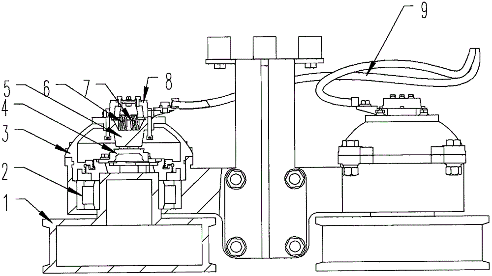
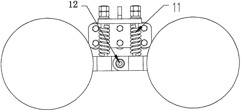
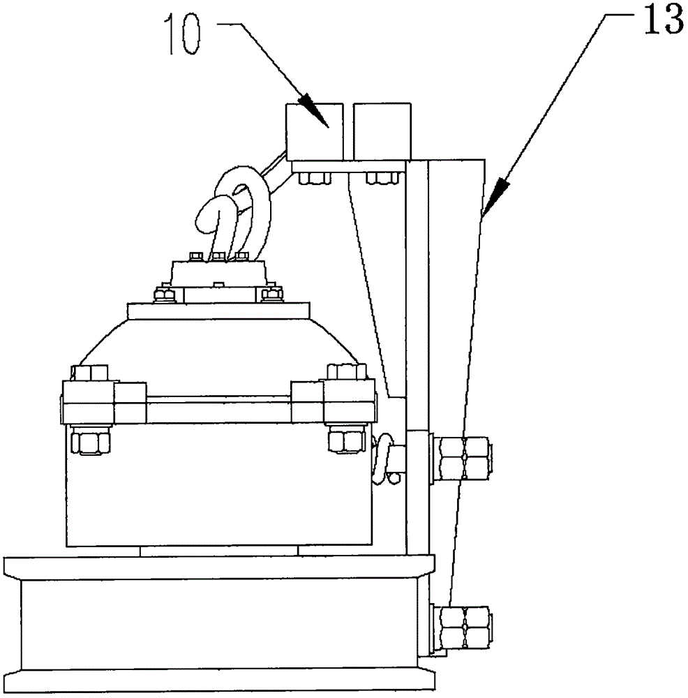
[0020] see Figure 1~3 , in an embodiment of the present invention, a roller slide line includes a conductive wheel 1, a conductive plate 4, a brush holder 5, a brush 6, a constant voltage compression spring 7, and an outer conductor 8; the conductive wheel 1 is mounted on the bearing 2 On the casing 3, the conductive wheel 1 is in rolling contact with the guide rail, and the conductive wheel 1 can roll freely; the conductive plate 4 is installed on the conductive wheel 1 and is in contact with the brush 6, and the conductive wheel 1 is rolled to make the conductive plate 4 and the brush 6 forms rolling friction, prevents the cable from being twisted, and can effectively conduct current for a long time. Due to the rolling of the conductive wheel 1, the conductive plate 4 and the brush 6 form rolling friction, so the wear of the brush 6 is very small, and the brush 6 can be avoided. Manual replacement can be used for a long time, saving manpower and energy, and at the same time...


PUM


Abstract

The invention discloses a roller sliding wire which comprises a conducting wheel, a conducting disc, a brush carrier, an electric brush, constant-pressure compressed springs and an outer electric conductor; the conducting wheel is arranged on a chassis through a bearing, and the conducting wheel is in rolling contact with a guide rail; the conducting disc is arranged on the conducting wheel and is in contact with the electric brush, and the electric brush is arranged in the brush carrier through at least two constant-pressure compressed springs, so that the conducting wheel rolls to drive the conducting disc to generate rolling friction between the conducting disc and the electric brush; a lead wire of the electric brush is fixed to the outer electric conductor, the outer electric conductor is connected with the interior of a travelling hoist through a connecting wire, and electricity on the guide rail is conducted into the travelling hoist. The built-in electric brush is adopted to conduct the electricity to the conducting wheel and the conducting wheel is in rolling contact with the guide rail accordingly, so that problem that a contact area between a siding wire on the travelling hoist and a sliding plate is reduced due to sliding wire oxidization, sliding wire deformation and unevenness of the surface of the sliding wire, and when heavy current passes through the sliding wire, the temperature rises sharply to allow the sliding plate to generate electric arcs, the sliding plate is subjected to thermal deformation or even is broken, which result in power failure and production stop is solved, and problems that the replacement cycle is short and high-altitude live-wire work maintenance is difficult are solved.

Description

technical field [0001] The invention relates to the technical field of mechanical equipment, in particular to a roller slide line. Background technique [0002] Bridge cranes, also known as cranes and cranes, are lifting equipment that are horizontally placed over workshops, warehouses and stockyards for material lifting. Because its two ends are located on tall concrete pillars or metal supports, it is shaped like a bridge. The bridge frame of the bridge crane runs longitudinally along the tracks laid on the elevated sides on both sides, which can make full use of the space under the bridge frame to lift materials without being hindered by ground equipment. It is a kind of hoisting machinery with the widest range and the largest number. This kind of crane is widely used in indoor and outdoor warehouses, factories, docks and open storage yards. [0003] The crane receiver is a device that supplies power to the crane. It has a collector brush that is fixed on the crane thr...

Claims


Application Information

Patent Timeline
Patent Type & Authority Applications(China)
IPC IPC(8): B66C13/12
CPCB66C13/12
Inventor 柴庆领马明洋
Owner CANGZHOU HUAHAI WIND POWER EQUIP SCI & TECH DEV
Learn More