A roof lifting device

A technology of lifting equipment and jib, which is applied in the direction of cranes, etc., can solve the problems of inconvenient installation of heavy objects in construction, poor wind resistance and stability, inconvenient installation of heavy objects, etc., and achieve cumbersome maintenance, The effect of large structural deformation and reasonable force

Active Publication Date: 2018-07-10
山东三箭资产投资管理有限公司 +2
View PDF8 Cites 0 Cited by
  • Summary
  • Abstract
  • Description
  • Claims
  • Application Information

AI Technical Summary

Problems solved by technology

[0002] At present, in the process of building construction, the traditional roof lifting devices often have the following problems: (1) The fuselage is bulky, the force is unbalanced, the bearing capacity is small, and the structural deformation is large; (2) The scope of application is limited, which is not convenient for narrow The construction of the site and the installation of heavy objects are in place; (3) the safety is poor, the sight is not good, and the operation is inconvenient; (4) the maintenance is cumbersome; (5) the wind resistance and stability are poor; (6) sensitive Poor reliability; (7) Unstable speed and inconvenient positioning
It also has problems such as poor safety, poor line of sight, inconvenient operation, cumbersome maintenance, poor wind resistance and stability, poor sensitivity and reliability, unstable speed, and inconvenient positioning.
[0005] Generally speaking, some existing roof lifting devices have the following problems: (1) The fuselage is bulky, the force is unbalanced, the bearing capacity is small, and the structural deformation is large; (2) The scope of application is limited, which is not convenient for construction in narrow sites (3) poor safety, poor sightlines, and inconvenient operation; (4) cumbersome maintenance; (5) poor wind resistance and stability; (6) relatively sensitive and reliable Poor; (7) Unstable speed and inconvenient positioning

Method used


Image

  • A roof lifting device
  • A roof lifting device
  • A roof lifting device

Examples


Embodiment Construction

[0028] In order to better understand the present invention, the present invention is described in detail below in conjunction with specific examples. It will, however, be evident that various changes and modifications can be made to the present invention without departing from the broader spirit and scope of the invention as defined in the appended claims. Therefore, the following examples have an illustrative rather than a limiting meaning.

[0029] Example:

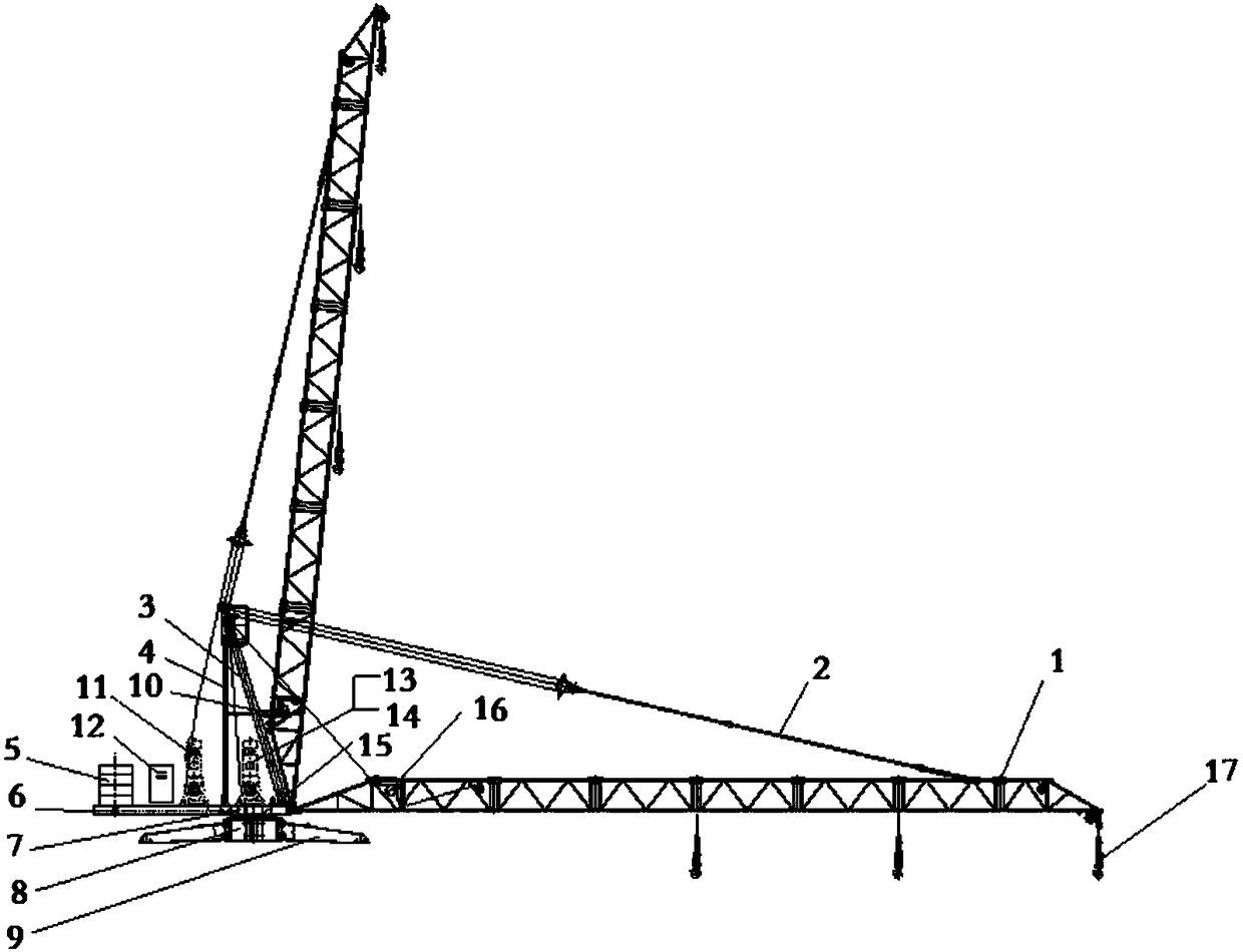
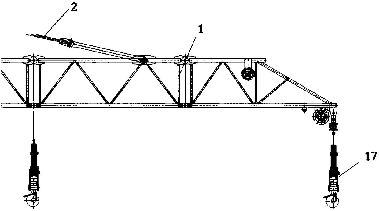
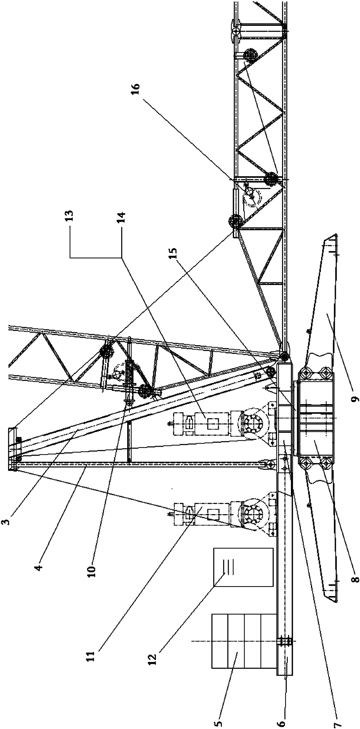
[0030] A roof lifting device such as Figure 1 to Figure 8 As shown, including the base, the base is provided with an upper turntable 7, the upper turntable 7 is connected with the tower, and the upper turntable 7 is equipped with a hoisting mechanism 13, a luffing mechanism 11, a turning mechanism 14 and an electrical control system 12; The mechanism 13, the luffing mechanism 11 and the slewing mechanism 14 are all equipped with safety protection devices; the luffing mechanism 8 is equipped with a frequency conversio...


PUM


Abstract

The invention relates to a roof lifting device. The device comprises a base, an upper rotary table is arranged on the base, and is connected with a tower frame, a lifting mechanism, an amplitude variation mechanism, a rotation mechanism and an electrical control system are mounted on the upper rotary table, the lifting mechanism, the amplitude variation mechanism and the rotation mechanism are each provided with a safety protection device, and the tower frame comprises a lifting arm and a supporting rod which are connected with the upper rotary table; one end of the supporting rod is connected with the upper rotary table, the other end of the supporting rod is connected with a tower cap and one end of a pull rod, one end of the lifting arm is connected with the upper rotary table and the other end of the tower cap, the other end of the lifting arm is connected with the other end of the pull rod, a backward-inclining-prevention device and a ring type weight limiter are arranged on the lifting arm, a rotation bearing device is arranged on the rotation mechanism, a balance arm connected with the lifting arm is arranged on the upper rotary table, and a balance weight device is arranged on the balance arm. The roof lifting device is good in safety, convenient to operate, good in wind resistance capacity, good in stability, good in sensitivity and reliability, stable in speed and convenient to place.

Description

technical field [0001] The invention belongs to the technical field of construction engineering, and in particular relates to a roof lifting device. Background technique [0002] At present, in the process of building construction, the traditional roof lifting devices often have the following problems: (1) The fuselage is bulky, the force is unbalanced, the bearing capacity is small, and the structural deformation is large; (2) The scope of application is limited, which is not convenient for narrow The construction of the site and the installation of heavy objects are in place; (3) the safety is poor, the sight is not good, and the operation is inconvenient; (4) the maintenance is cumbersome; (5) the wind resistance and stability are poor; (6) sensitive Poor reliability; (7) Unstable speed and inconvenient positioning. [0003] The patent number is "ZL201220187781.6", the authorized announcement number is "CN202575758U", and the Chinese utility model patent named "a roof cr...

Claims


Application Information

Patent Timeline
Patent Type & Authority Patents(China)
IPC IPC(8): B66C23/06B66C23/82B66C23/84
CPCB66C23/06B66C23/82B66C23/84
Inventor 康卫东郭克光王洪彬江华张云松孙广花张雯婷徐彬
Owner 山东三箭资产投资管理有限公司
Why Eureka
Try Eureka