Construction method for fiberglass reinforced plastic mortar pipe culvert of roads

A technology of FRP sand inclusion and construction method, which is applied to the bottom layer of roads, buildings, etc., can solve problems such as poor control, collapsed FRP sand inclusion pipes, and uniformity of force, and achieve the effect of ensuring stability

Active Publication Date: 2017-02-22
HEBEI UNIV OF TECH
View PDF7 Cites 11 Cited by
  • Summary
  • Abstract
  • Description
  • Claims
  • Application Information

AI Technical Summary

Problems solved by technology

This method is prone to landslides due to full-section excavation, and it is difficult to control the uniformity of force on the FRP sand-filled pipe

Method used


Image

  • Construction method for fiberglass reinforced plastic mortar pipe culvert of roads
  • Construction method for fiberglass reinforced plastic mortar pipe culvert of roads
  • Construction method for fiberglass reinforced plastic mortar pipe culvert of roads

Examples


Embodiment 1

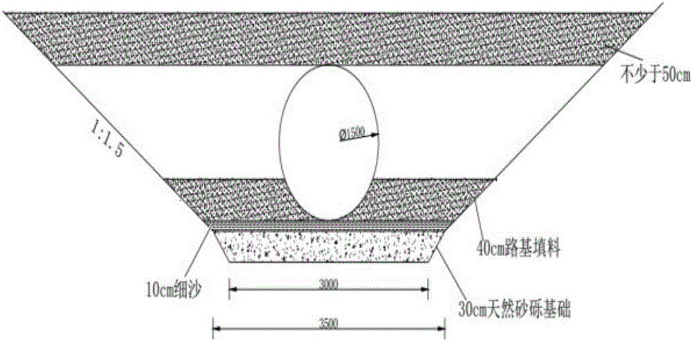
[0046] The diameter of the FRP sand-filled pipe in this embodiment is 1.5m. It is used for the drainage of highway culverts. The soil at the construction site is clay, and the height of the upper end of the FRP sand-filled pipe is less than 1m.

[0047] The specific construction process is:

[0048] The section form of the foundation pit adopts the method of sloping and digging. The two sides of the foundation pit are sloped according to the ratio of slope height: width = 1:1.5. When the diameter is 1.5m, the excavation width of the foundation pit is 3m, and the width of the base replacement with natural gravel is 3.5m (adding 0.5m to the foundation pit excavation width of 3m is 3.5m) (see figure 2 ).

[0049] During base treatment, 30cm natural gravel is used for replacement, and the compaction degree is 98%, forming a 30cm natural gravel foundation. After the base is replaced, 10cm of standard fine sand is firstly spread on the base, and then on the standard fine sand, loe...

Embodiment 2

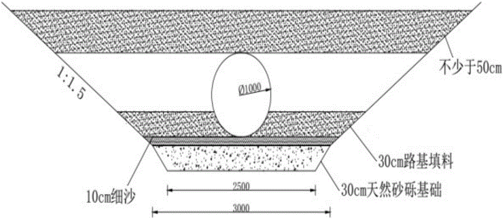
[0055] The diameter of the FRP sand-filled pipe in this embodiment is 1 m. It is used for drainage of highway culverts. The soil at the construction site is clay, and the height of the upper end of the FRP sand pipe is less than 1m.

[0056] The specific construction process is:

[0057] The section form of the foundation pit adopts the method of sloping and digging. The two sides of the foundation pit are sloped according to the ratio of slope height: width = 1:1.5. When the diameter is 1m, the excavation width of the foundation pit is 2.5m, and the width of the base replacement with natural gravel is 3m (adding 0.5m to the foundation pit excavation width of 2.5m is 3m) (see image 3 ).

[0058] During base treatment, 30cm natural gravel is used for replacement, and the compaction degree is 98%, forming a 30cm natural gravel foundation. After the base is replaced, spread about 10cm of standard fine sand on the base, and then fill with loess as subgrade filler on the standa...


PUM

PropertyMeasurementUnit
diameteraaaaaaaaaa
diameteraaaaaaaaaa

Abstract

The invention relates to a construction method for a fiberglass reinforced plastic mortar pipe culvert of roads. According to the method, if substrate soil has relatively poor quality or has relatively high water content during substrate treatment, natural gravel soil is adopted to replace and fill for 30cm, and the substrate compactness is controlled to be not less than 98 percent; when standard fine sands are filled with loess, the loess filling height is not lower than 30cm, and the compactness is controlled to be 96 percent, so that the subgrade soil stability is ensured. Before the fiberglass reinforced plastic mortar pipe is placed, the fiberglass reinforced plastic mortar pipe is sleeved with positions, away from two sides of the center of the fiberglass reinforced plastic mortar pipe by not less than 1.5cm, with a steel ring casing with a rubber ring; then, steel rings are fixed on the loess by virtue of anchor bolts, and the fiberglass reinforced plastic mortar pipe is fixed by using the steel rings, so that the fiberglass reinforced plastic mortar pipe is prevented from being greatly migrated due to water flushing during later use. Medium-coarse sand is selected as the backfill material in two sides of the fiberglass reinforced plastic mortar pipe, and the compactness is controlled to be over 96 percent, so that the fiberglass reinforced plastic motor pipe is uniformly stressed, and the construction quality can be remarkably improved.

Description

technical field [0001] The invention belongs to the technical field of construction methods for road glass fiber reinforced plastic sand pipe culverts, and relates to a construction method for road glass steel sand pipe culverts. Background technique [0002] Now FRP sand-filled pipes are more and more widely used in road construction. The existing construction method is to carry out construction in the way of pipe jacking. The excavation of the working face is carried out by hand-digging, and then the FRP sand-filled pipes are removed with a jack. Make jacking. After the jacking is completed, seal the outer space of the FRP sand-filled pipe with cement concrete, and fill and grout each FRP sand-filled pipe one by one from one end to the other through the reserved grouting holes. The grouting effect is dually controlled by the grouting pressure and the visual effect. This method is prone to landslides due to full-section excavation, and it is difficult to control the unifo...

Claims


Application Information

Patent Timeline
Patent Type & Authority Applications(China)
IPC IPC(8): E01F5/00
CPCE01F5/005
Inventor 魏连雨汪洋陈兆南张静郑彦军梁筱张国盘李娜檀奥龙
Owner HEBEI UNIV OF TECH
Why Eureka
Try Eureka