Improved pouring draught fan foundation pit

An improved and foundation pit technology is applied in the field of fan foundation pit and improved pouring fan foundation pit, which can solve the problems of large concrete slump, concrete waste, and reduce concrete water-cement ratio, so as to ensure the pouring quality and increase flexibility. performance, improve efficiency

Inactive Publication Date: 2017-02-22
王振宁
View PDF5 Cites 0 Cited by
  • Summary
  • Abstract
  • Description
  • Claims
  • Application Information

AI Technical Summary

Problems solved by technology

[0002] The existing pouring construction generally uses a concrete delivery pump truck; the mechanical principle of the concrete delivery pump truck is that the concrete pistons are respectively connected with the piston rods of the main oil cylinder, and under the action of the hydraulic oil of the main oil cylinder, they reciprocate. When one cylinder advances, the other cylinder moves forward. Reverse; the outlet of the concrete cylinder is connected to the hopper, one end of the distribution valve is connected to the outlet, and the other end can be connected to the swing arm through the spline shaft, and can swing left and right under the action of the swing cylinder; The concrete cylinder in the suction stroke is connected to the distribution valve, and the concrete cylinder in the push stroke is connected to the hopper, so that the concrete in the pipeline is drawn back to the hopper; when the concrete piston retreats to the end of the stroke, the reversing device in the water tank is triggered, The direction of the main oil cylinder is changed, and the direction of the swing oil cylinder is changed at the same time, so that the distribution valve is connected with the concrete cylinder, and the concrete cylinder is connected with the hopper. ) requires a large slump of concrete, which is not conducive to reducing the water-cement ratio of concrete; 2) the phenomenon of concrete waste is serious; 3) the concrete pouring time is too long to meet the requirements of mass concrete for pouring continuity; 4) mechanical reliability The performance is not high, and it is easy to fail and block the pipe; 5) The requirements for the pouring terrain are relatively high

Method used


Image

  • Improved pouring draught fan foundation pit
  • Improved pouring draught fan foundation pit
  • Improved pouring draught fan foundation pit

Examples


Embodiment Construction

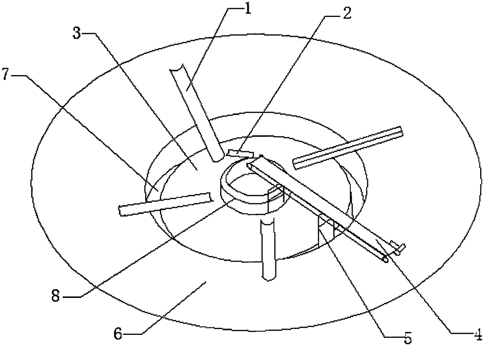
[0014] Such as figure 1 As shown, the improved pouring fan foundation pit of the present invention includes a foundation pit 6 and a template 7 installed in the foundation pit 6; the template 7 is constructed by a plurality of steel bars (not shown); the foundation pit 6 is provided with a foundation 3 in the center; a foundation ring 8 is provided in the center of the foundation 3; a steel pipe (not shown) of the same height as the template 7 is welded to the edge of the template 7; a door-type bracket 5 is installed on the steel pipe; A belt conveyor 4 is installed between the door-shaped bracket 5 and the base ring 8; four long chutes 1 are arranged between the foundation pit 6 and the base ring 8; the belt conveyor 4 has a short Chute 2.

[0015] The belt conveyor 4 is hoisted to the door-shaped bracket 5 by a crane, and the front end of the belt conveyor 4 is set in the center of the foundation ring 8, and the end of the belt conveyor 4 is set at a position not less than 2 ...


PUM


Abstract

The invention discloses an improved pouring draught fan foundation pit which comprises a foundation pit body and a template mounted in the foundation pit, wherein the template is formed by putting up a plurality of rebars; a foundation is arranged in the center of the foundation pit body; a foundation ring is arranged in the center of the foundation center; a steel pipe as high as the template is welded at the edge of the template; a door type bracket is mounted on the steel pipe; a belt conveyer is mounted between the door type bracket and the foundation ring; a plurality of long chutes are arranged between the foundation pit body and the foundation ring at intervals; and a short chute is mounted at the bottom of the front end of the belt conveyer. The improved pouring draught fan foundation pit increases pouring flexibility; continuous concrete construction can be ensured under a low temperature to ensure concrete pouring quality; and pouring is free of terrain limitation.

Description

Technical field [0001] The invention relates to a fan foundation pit, in particular to an improved pouring fan foundation pit, and belongs to the technical field of construction machinery. Background technique [0002] The existing pouring construction generally uses a concrete delivery pump truck; the mechanical principle of the concrete delivery pump truck is that the concrete pistons are connected to the piston rods of the main cylinders respectively, and under the action of the hydraulic oil of the main cylinders, they reciprocate. One cylinder moves forward, and the other cylinder Backward; the outlet of the concrete cylinder is connected with the hopper. One end of the distribution valve is connected to the discharge port, and the other end can be connected to the swing arm through the spline shaft. Under the action of the swing cylinder, it can swing left and right; The concrete cylinder in the suction stroke is connected with the distribution valve, and the concrete cylin...

Claims


Application Information

Patent Timeline
Patent Type & Authority Applications(China)
IPC IPC(8): E02D27/42E02D15/02
CPCE02D27/425E02D15/02E02D2250/0023
Inventor 王振宁
Owner 王振宁
Why Eureka
Try Eureka