Cyclone pump impeller with spiral structure at front end and design method thereof

A technology of helical structure and design method, which is applied to the components, pumps, and pump elements of pumping devices for elastic fluids, can solve the problems of low efficiency and large hydraulic loss of the pump, and achieves reduction of energy loss and improvement of work efficiency. The effect of efficiency and good economic benefits

Active Publication Date: 2017-02-22
ZHEJIANG SCI-TECH UNIV
View PDF6 Cites 12 Cited by
  • Summary
  • Abstract
  • Description
  • Claims
  • Application Information

AI Technical Summary

Problems solved by technology

[0004] However, due to the limitation of the structure, the swirl pump also has the following disadvantages: due to th

Method used


Image

  • Cyclone pump impeller with spiral structure at front end and design method thereof
  • Cyclone pump impeller with spiral structure at front end and design method thereof
  • Cyclone pump impeller with spiral structure at front end and design method thereof

Examples


Embodiment 1

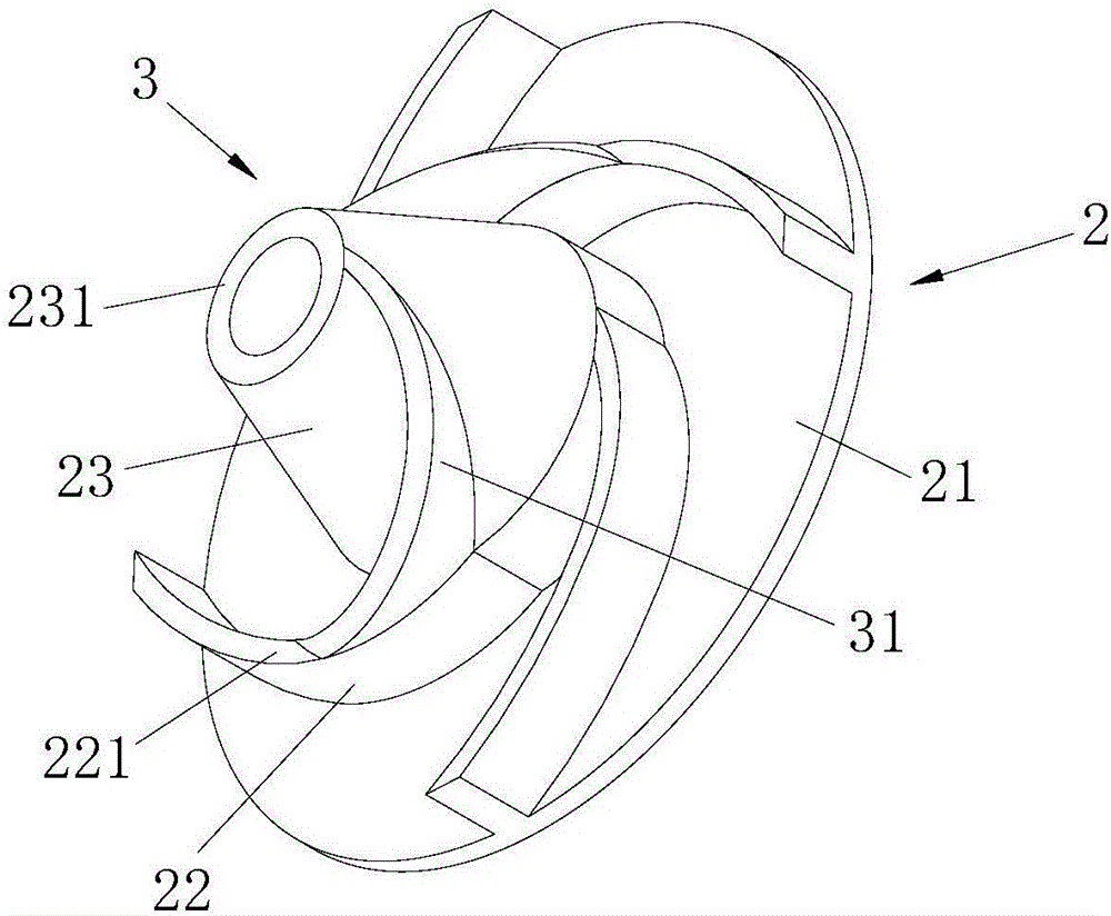
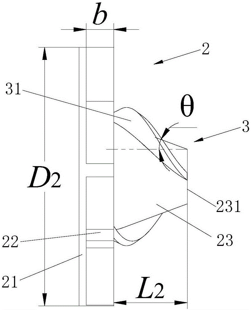
[0050] Embodiment one: if Figure 1-6 As shown, this embodiment includes a swirl pump impeller 2 and a volute 1 with a vane cavity 11. The swirl pump impeller 2 is a semi-open impeller, and the semi-open impeller includes a front cover plate 21, impeller blades 22 and a hub. 23; The part of the volute 1 far away from the front cover 21 is provided with a vane cavity opening 12, the semi-open impeller is installed in the vane cavity 11, and the part of the hub 23 far away from the front cover 21 is the hub front end 231, and the hub front end 231 It is set toward the opening 12 of the blade cavity, and the distance between the front end 231 of the hub and the opening 12 of the blade cavity is L 1. The outer surface of the wheel hub 23 is a truncated cone structure (or called a truncated cone structure). The area of ​​the upper bottom surface of this truncated circular structure is less than the area of ​​the lower bottom surface, so the wheel hub 23 is fixed with the front cov...

Embodiment 2

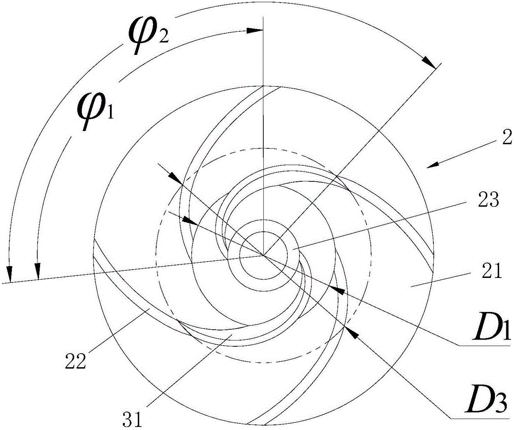
[0080] Embodiment 2: The molded line of the helical blade 31 is a helical line, and the helical line takes the center of the lower bottom surface of the hub 23 as the origin, and establishes a three-dimensional coordinate system, wherein the x-axis and the y-axis are located on the lower bottom surface, and the z-axis direction is perpendicular to x Axis and y-axis, and consistent with the hub 23 axis direction, if the starting point of the spiral blade 31 is point A, the end point of the spiral blade is point B, and the coordinates of point A are ( 0, L2), the coordinates of point B are ( 0), any point on the space curve connecting point A and point B is point C, the projection of point C on the bottom surface is C', the line connecting C' and the origin is OC', and the clip between OC' and the positive direction of the x-axis Angle is Then the coordinates of point C are In the formula:

Embodiment 3

[0081] Embodiment 3: The number of helical blades 31 is equal to the number of impeller blades 22 , and the front end of each impeller blade 22 is provided with helical blades 31 in one-to-one correspondence.


PUM


Abstract

The invention discloses a design method of a cyclone pump impeller with a spiral structure at the front end. A semi-open impeller includes a front cover plate, an impeller blade and a hub; the outer surface of the hub is of a round table structure; the hub is fixed to the front cover plate through the lower bottom surface; the end part, far from the front cover plate, of the impeller blade is a blade front end; the spiral structure is arranged at the blade front end; the inlet diameter of the impeller blade is D1; the outlet diameter of the impeller blade is D2; the outer diameter of a spiral blade is D3; the outlet width of the impeller blade is b; the outlet angle of the impeller blade is beta 2; the outlet angle of the spiral blade is beta 4; the axial length of the spiral blade is L2; the wrap angle of the propeller blade is delta 1; and the wrap angle of the spiral blade is delta 2. The design method can effectively improve the pump internal flowing conditions, reduces internal circulating flows, reduces the energy loss, greatly improves the working efficiency of a cyclone pump, and gains excellent economic benefits in large-scale industrial production application. The invention discloses the cyclone pump impeller with the spiral structure at the front end.

Description

technical field [0001] The invention relates to an impeller, in particular to a swirl pump impeller with a spiral structure at the front end. The invention relates to a design method of an impeller, in particular to a design method of a swirl pump impeller with a spiral structure at the front end. Background technique [0002] In factory applications, the impurity pump is a pump body that transports solid media. The swirl pump is a non-clogging pump used to transport solid-liquid media. It is named for the vortex generated by the fluid in the pump chamber during operation. The impeller of the swirl pump is open or semi-open, and the impeller retracts to the back chamber of the pump casing, which provides good conditions for the solid medium to pass through the pump body. When the swirl pump is working, the medium near the top of the impeller outlet will form a through flow due to the large centrifugal force, and the medium in the middle of the impeller will form a circulat...

Claims


Application Information

Patent Timeline
IPC IPC(8): F04D29/22F04D29/24
CPCF04D29/2244F04D29/245
Inventor 李晓俊项佳梁王艳萍朱祖超李昳
Owner ZHEJIANG SCI-TECH UNIV
Why Eureka
Try Eureka