An annular pipe sealing ring for ultra-low temperature dynamic sealing and its processing method

A technology of dynamic sealing and processing method, applied in the direction of engine sealing, engine components, mechanical equipment, etc., can solve the problems of inability to apply dynamic sealing, bursting, tearing, sealing ring failure, etc., to reduce processing costs and improve accuracy. and strength, good sealing effect

Active Publication Date: 2018-05-04
苏州先创流体控制技术有限公司 +1
View PDF9 Cites 0 Cited by
  • Summary
  • Abstract
  • Description
  • Claims
  • Application Information

AI Technical Summary

Problems solved by technology

[0005] However, this semi-open ultra-low temperature sealing ring with a built-in metal spring ring has the following disadvantages: it is mainly suitable for static sealing and sliding sealing, and it cannot be applied to dynamic sealing
Because when the two sealing end faces are separated from each other, the pressure in the opening is greater than the pressure on the back of the seal, and the two lips 103 of the outer ring 101 will be tightly attached to the sealing end faces by the pressure. With the separation of the sealing end faces, the outer ring 101 The two lips 103 are burst and torn, causing the sealing ring to fail

Method used


Image

  • An annular pipe sealing ring for ultra-low temperature dynamic sealing and its processing method
  • An annular pipe sealing ring for ultra-low temperature dynamic sealing and its processing method
  • An annular pipe sealing ring for ultra-low temperature dynamic sealing and its processing method

Examples


Embodiment 1

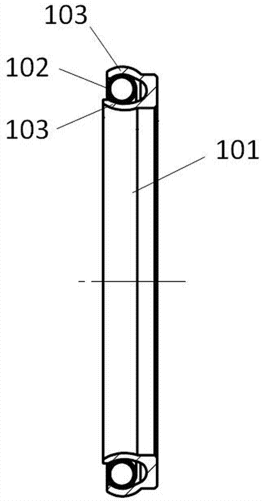
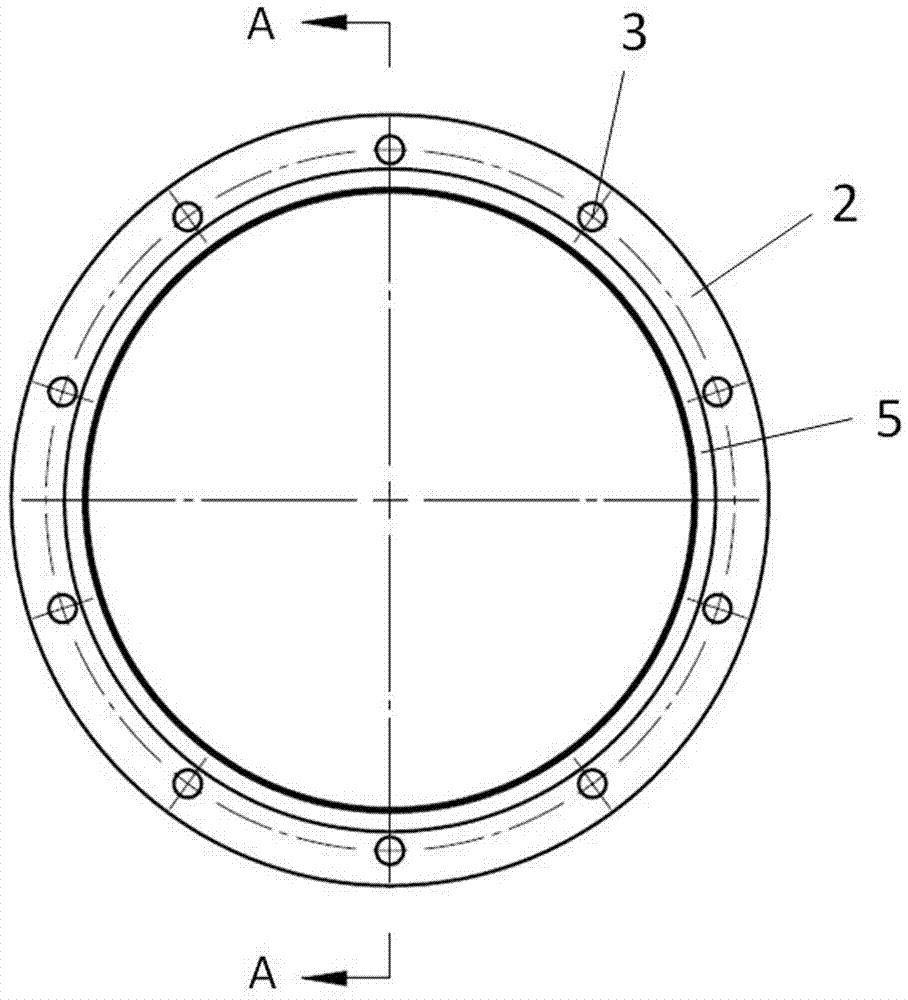
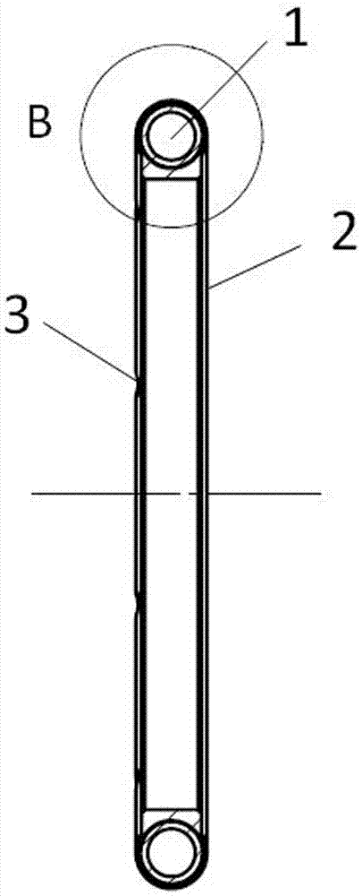
[0032] A first embodiment of an annular pipe sealing ring for ultra-low temperature dynamic sealing of the present invention, such as Figure 2 to Figure 4As shown, it includes a tube 2 provided with a hollow cavity 1, and a group of air inlet holes 3 arranged on the tube 2, the tube 2 is annular, and a support 4 is provided in the cavity 1; the support 4 is an annular rod made of low temperature resistant material, the material diameter of the annular rod is smaller than the inner diameter of the pipe 2; the pipe 2 is provided with a ring-shaped support 5, and the support 5 is connected to the mounting surface for externally installing the annular pipe sealing ring , the support 5 is set on the inner ring surface of the tube 2; a group of air inlets 3 is not less than 2 in number and distributed in an annular array, which are set on the side end or the outer ring surface of the tube 2 according to the direction of the high-pressure fluid ; The tube 2 is made of PTFE or PCTFE ...

Embodiment 2

[0045] A second embodiment of the annular pipe sealing ring used for ultra-low temperature dynamic sealing of the present invention, such as Figure 5 and Figure 6 As shown, it includes a tube 2 provided with a hollow cavity 1, and a group of air inlet holes 3 arranged on the tube 2, the tube 2 is annular, and a support 4 is provided in the cavity 1; the support 4 is an annular support tube made of low temperature resistant material, the material diameter of the annular support tube is smaller than the inner diameter of the tube 2, the tube 2 is a round tube, and the material diameter (the outer diameter of the cross section of the round tube) is 60 mm, the ring tube The outer diameter of the sealing ring is 2m, and the one-sided gap between the annular support pipe and the pipe 2 is 5.5mm; The mounting surfaces are connected, and the support 5 is arranged at the side end of the pipe 2; the number of the group of air inlets 3 is not less than 2, and they are distributed in a...

Embodiment 3

[0048] A third embodiment of an annular pipe sealing ring for ultra-low temperature dynamic sealing of the present invention, such as Figure 7 and Figure 8 As shown, it includes a tube 2 with a hollow cavity 1, and a group of air inlet holes 3 arranged on the tube 2. The tube 2 is annular, and a support 4 is provided in the cavity 1. The support 4 is a ring-shaped spring ring formed by spirally winding metal sheets; the tube 2 is a round tube, and the material diameter (the outer diameter of the cross-section of the round tube) is 4mm, the outer diameter of the annular tube sealing ring is 6mm, and the spring ring The one-sided gap between the pipe 2 and the pipe 2 is 0.05mm; the pipe 2 is provided with a ring-shaped support 5, and the support 5 is connected with the mounting surface for externally installing the annular pipe sealing ring, and the support 5 is arranged on the pipe 2 The outer ring surface of the outer ring surface; the number of the group of air intake hole...


PUM


Abstract

The invention discloses an annular pipe sealing ring used for ultralow-temperature dynamic sealing. The annular pipe sealing ring comprises a pipe and a group of air inlet holes, wherein the pipe is provided with a hollow cavity, and the air inlet holes are formed in the pipe. The pipe is annular, and the hollow cavity of the pipe is internally provided with a supporting piece. The sealing ring with the design can be made of a relatively flexible low-temperature-resistant material, and the sealing effect is ensured; meanwhile, the annular pipe sealing ring not only can be used for static sealing and sliding sealing under an ultralow-temperature working condition but also can be used for dynamic sealing under the ultralow-temperature working condition; when no fluid pressure exists in the inner cavity, the thin-wall pipe is supported through stable supporting force provided by the supporting piece inside the inner cavity, and crushing and failure of the pipe are prevented; when high-pressure fluid enters the inner cavity of the pipe and the pressure difference is produced, the thin-wall pipe has enough deformation capability, can be closely attached to the metal surface and is good in sealing effect; and in addition, when the two sealing end surfaces are relatively separated, the sealing ring has enough strength to bear the pressure difference alone, and breaking caused by pulling, bursting and failure are avoided.

Description

technical field [0001] The invention relates to the technical field of ultra-low temperature fluid sealing, in particular to an annular pipe sealing ring used for ultra-low temperature dynamic sealing. Background technique [0002] The ultra-low temperature sealing ring is mainly used for the sealing of ultra-low temperature fluids, such as LNG, liquid hydrogen, liquid oxygen and liquid nitrogen, etc. It can be used for the sealing of ultra-low temperature storage tanks and filling ports of LNG vehicles and ships, and the liquid fuel storage of rockets and aviation aircraft. Sealing of tanks and fuel lines, and other occasions where cryogenic sealing is required. [0003] The most common type of ultra-low temperature sealing rings in the market is the O-ring. The disadvantage of this type of sealing ring is that the sealing rings made of materials with good sealing effect, such as fluorine rubber, nitrile rubber or silica gel, cannot withstand Ultra-low temperature, its ela...

Claims


Application Information

Patent Timeline
Patent Type & Authority Patents(China)
IPC IPC(8): F16J15/06
CPCF16J15/068
Inventor 白慧星
Owner 苏州先创流体控制技术有限公司
Why Eureka
Try Eureka