Evaporator having vertical arrangement of header pipe for vehicle air conditioner

A collecting tube and evaporator technology, applied in evaporator/condenser, vehicle parts, applications, etc., can solve the problems that condensed water cannot be removed, heat transfer area cannot be expanded, etc., so as to prevent scattering and maximize heat exchange efficiency Effect

Inactive Publication Date: 2017-02-22
DONGHWAN IND CORP
View PDF10 Cites 1 Cited by
  • Summary
  • Abstract
  • Description
  • Claims
  • Application Information

AI Technical Summary

Problems solved by technology

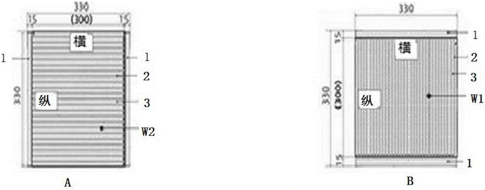
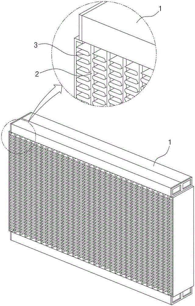
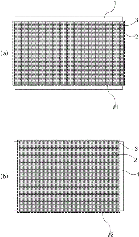
[0015] That is, the evaporator of the prior art has a structure in which the condensed water falling on the surfaces of the tubes 2 and the fins 3 in the vertical direction is removed because the tubes 2 and the fins 3 are arranged in the vertical direction. If the tubes 2 and the fins 3 Arranged in the horizontal direction, there is a problem that the condensed water cannot be removed and the air supply pressure and the cooling energy of the blower are scattered together. Therefore, the pipes 2 must be arranged in the vertical direction
[0016] Therefore, the evaporator of the prior art can only be arranged in a vertical direction in order to discharge the condensed water generated on the surface of the tubes and fins, so that the heat transfer area cannot be enlarged in the same overall area.

Method used


Image

  • Evaporator having vertical arrangement of header pipe for vehicle air conditioner
  • Evaporator having vertical arrangement of header pipe for vehicle air conditioner
  • Evaporator having vertical arrangement of header pipe for vehicle air conditioner

Examples


Embodiment Construction

[0054] Below, the embodiment of the present invention will be described in more detail with reference to the accompanying drawings. In explaining the present invention, detailed descriptions of common functions or structures of related disclosed contents are omitted.

[0055] Embodiments according to the concept of the present invention can be modified in various ways and have various forms. Therefore, specific embodiments are shown in the drawings and described in detail through this specification or application. However, the present invention is not limited to a specific embodiment, and all modifications, equivalents, and substitutions belonging to the spirit and technical scope of the present invention are included.

[0056]A structure "connected" or "accessed" to another structure means that it is directly connected or accessed to another structure or is connected or accessed through another structure. In contrast, a structure that is "directly connected" or "directly acc...


PUM


Abstract

The present invention relates to an air conditioning evaporator for a vehicle which is connected to a refrigeration cycle system constituting an air conditioner and which provides heat of vaporization while supplying a cold air to provide cold air by heat exchange with air supplied from the fan. The evaporator comprises a pair of header pipes disposed in opposing form for the supply of refrigerant from said refrigeration cycle system, providing a circulation path and discharging refrigerant to complete heat exchange; a plurality of tubes which are provided so as to be transparently connected in the form of passing through the pair of header pipes and provided in the longitudinal direction of the head pipes so as to move the refrigerant flowing into the inflow port of the head pipes to the discharge port of the head pipes in a zigzag shape to simultaneously carry out heat exchange with the air; and cooling fins which are disposed among the above tubes so as to cool the evaporation heat from the tubes when unchoking the air provided by the tubes. The tubes are arranged in a vertical direction and the tubes are arranged in a horizontal direction, the length of the tubes being larger than the length of the head pipes and forming a rectangle.

Description

technical field [0001] The invention relates to an air-conditioning evaporator, in particular to a vehicle air-conditioning evaporator which is vertically arranged with a collecting pipe to enlarge the heat transfer area compared with the existing evaporator structure. Background technique [0002] Generally, an air conditioner is installed in a vehicle to maintain a fresh state in a room polluted by the breathing of passengers, the state of the outside air, or changes in the temperature of the outside, or to cool or heat the room to maintain the environment suitable for passengers. body temperature, thereby forming a pleasant indoor environment. [0003] When the above-mentioned air conditioner performs heating, the cooling water heated by the engine is poured into the heater core to exchange heat with the air of the blower to supply warm air, and when performing cooling, the evaporator that constitutes the refrigeration cycle system of the refrigerant is used The heat of ...

Claims


Application Information

Patent Timeline
Patent Type & Authority Applications(China)
IPC IPC(8): F25B39/02
CPCF25B39/02F25B2339/02B60H1/3227F28F17/005F28D1/05391F28F1/126F28D2021/0085F25B39/00F25D21/14
Inventor 高东焕
Owner DONGHWAN IND CORP
Why Eureka
Try Eureka