Optical fiber temperature sensor used for oil-immersed transformer winding

An oil-immersed transformer, optical fiber temperature technology, applied to thermometers, thermometers, instruments and other directions with physical/chemical changes, can solve the problems of limited test range, unreliability, installation space requirements, etc., to achieve simple and reliable packaging, insertion The effect of low losses and no temperature drift

Inactive Publication Date: 2017-02-22
南通海轶锶换热设备有限公司
View PDF0 Cites 0 Cited by
  • Summary
  • Abstract
  • Description
  • Claims
  • Application Information

AI Technical Summary

Problems solved by technology

Considering that the bare fiber grating is particularly fragile, especially its poor shear resistance, directly using it as a temperature sensor is not suitable for sensor layout and harsh service environments. Therefore, packaging the bare fiber grating is to promote the fiber grating as a temperature sensor. an inevitable part of the application
[0004] The traditional temperature measurement methods in the power industry generally include thermocouples / thermal resistances installed at temperature measurement points or some point-type temperature measurement devices, infrared temperature measurement devices have manual inspection, etc. These methods are limited by their own temperature measurement principles Inevitably, there are some insurmountable defects, such as only reflecting the temperature of local locations, the test range is limited; there are requirements for installation space, cumbersome and unreliable; susceptible to electromagnetic interference, affecting accuracy, etc.
Therefore, the traditional temperature measurement method and equipment cannot meet the advantages of adapting to various harsh chemical environments in the power industry and being free from electromagnetic interference. It can directly contact various contacts and connection points of electrical equipment to sense the temperature at the location. monitoring needs

Method used


Image

  • Optical fiber temperature sensor used for oil-immersed transformer winding
  • Optical fiber temperature sensor used for oil-immersed transformer winding
  • Optical fiber temperature sensor used for oil-immersed transformer winding

Examples


Embodiment 1

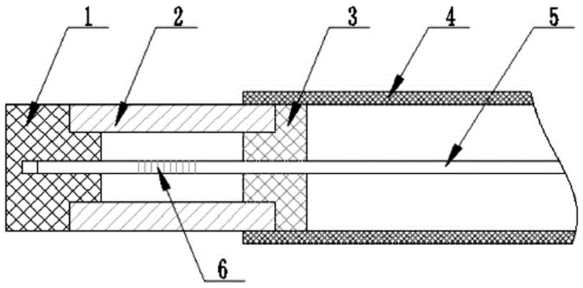
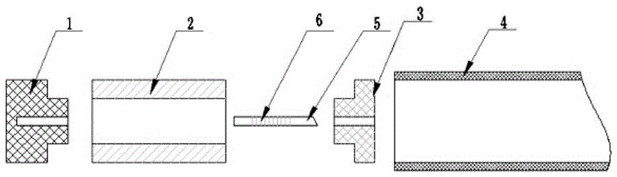
[0034] Figure 1 is a schematic diagram of the overall structure of an optical fiber temperature sensor for an oil-immersed transformer winding in the present invention; Figure 2 is a schematic diagram of the split structure of an optical fiber temperature sensor for an oil-immersed transformer winding in the present invention;

[0035] As shown in Figure 1 and Figure 2: an optical fiber temperature sensor for an oil-immersed transformer winding, it is characterized in that: the optical fiber temperature sensor is composed of two protective tubes 2 and 4, two fixed caps 1 and 3 and transmission optical fiber 5 The transmission fiber 5 is provided with a fiber grating 6; the two protection tubes 2 and 4 are respectively connected to the two fixing caps 1 and 3, and the two protection tubes 2 and 4 are hollow; the One of the fixed caps 3 is provided with a central through hole 11, and the other fixed cap 1 is provided with a groove 12, and the transmission optical fiber 5 passes t...

Embodiment 2

[0052] Fig. 1 is a schematic diagram of the overall structure of an optical fiber temperature sensor for an oil-immersed transformer winding in the present invention; Fig. 2 is

[0053] A schematic diagram of a split structure of an optical fiber temperature sensor for an oil-immersed transformer winding in the present invention;

[0054] As shown in Figure 1 and Figure 2: an optical fiber temperature sensor for oil-immersed transformer windings, characterized in that: the optical

[0055] The fiber temperature sensor is composed of two protective tubes 2 and 4, two fixed caps 1 and 3 and a transmission fiber 5; the transmission fiber 5 is provided with a fiber grating 6; the two protection tubes 2 and 4 are respectively connected with two Two fixed caps 1 and 3 are connected, and the two protective tubes 2 and 4 are hollow; one of the fixed caps 3 is provided with a central through hole 11, and the other fixed cap 1 is provided with a groove 12 for transmission The optical f...

Embodiment 3

[0068] Figure 1 is a schematic diagram of the overall structure of an optical fiber temperature sensor for an oil-immersed transformer winding according to the present invention.

[0069] Fig. 2 is a schematic diagram of a split structure of an optical fiber temperature sensor for an oil-immersed transformer winding according to the present invention.

[0070] As shown in Figure 1 and Figure 2: an optical fiber temperature sensor for an oil-immersed transformer winding, it is characterized in that: the optical fiber temperature sensor is composed of two protective tubes 2 and 4, two fixed caps 1 and 3 and transmission optical fiber 5 Composition; the transmission fiber 5 is provided with a fiber grating 6; the two protection tubes 2 and 4 are respectively connected to the two fixing caps 1 and 3, and the two protection tubes 2 and 4 are hollow; the One of the fixed caps 3 is provided with a central through hole 11, and the other fixed cap 1 is provided with a groove 12, and th...


PUM


Abstract

An optical fiber temperature sensor used for an oil-immersed transformer winding is disclosed. The sensor is characterized in that the optical fiber temperature sensor is formed by two protection pipes, two fixed caps and a transmission fiber; a fiber bragg grating is arranged in the transmission fiber; the two protection pipes are connected to the two fixed caps respectively, and the two protection pipes are in a hollow state; a center through hole is arranged in one fixed cap and a groove is arranged in another fixed cap; the transmission fiber is penetrated from a center through hole of the protection pipe, then enters into another protection pipe through the center through hole of the fixed cap and enters into the fixed cap through the protection pipe and the groove connected to another fixed cap; components are formed through one of mechanical connection, bonding agent connection and welding connection or combination of the above connection modes. The sensor has advantages that packaging is simple; installation and interchange are convenient; there is no error; temperature drift is not generated during long-term operation; and recalibration is not needed.

Description

technical field [0001] The invention relates to the technical field of optical fiber grating sensing, relates to a temperature sensor based on optical fiber gratings, and in particular to an optical fiber temperature sensor for oil-immersed transformer windings for temperature measurement in an electric high-voltage environment. Background technique [0002] During the operation of power equipment, it is affected by factors such as electricity, heat, natural environment, long-term work, overload work, etc., which can easily lead to equipment aging, performance degradation, lower reliability, and even endanger the safe operation of the system. For example, due to poor contact in transformers, switch cabinets, ring network cabinet contacts or cable joints, the contact resistance increases, resulting in excessive temperature rise of the contacts, causing fires, explosions and other accidents. Therefore, it is necessary to carry out real-time and online monitoring of power e...

Claims


Application Information

Patent Timeline
Patent Type & Authority Applications(China)
IPC IPC(8): G01K11/32G01K11/3206
CPCG01K11/32
Inventor 程海霞
Owner 南通海轶锶换热设备有限公司
Why Eureka
Try Eureka