Initiative detection device for oil pollution degree

A technology for oil pollution degree and active detection, which is applied in the direction of measuring devices, preparation of test samples, analysis of suspensions and porous materials, etc., and can solve problems such as high cost, difficult operation, and complex structure

Inactive Publication Date: 2017-02-22
陈盈洁
View PDF7 Cites 2 Cited by
  • Summary
  • Abstract
  • Description
  • Claims
  • Application Information

AI Technical Summary

Problems solved by technology

Therefore, in view of the problems of the existing oil pollution detection devices such as complex structure, difficult operation, high cost, and selectivity and pertinence of the detection method, the present invention is based on the oil pollution degree detection standard system of ISO4406, Using the basic principles of fluid mechanics, an active detection device for oil pollution is proposed, which is mainly composed of an oil inlet cover, a circular shell, a filter piston for 15um particles, a filter piston for 5um particles, a return spring, a spoiler, and a throttle body. It is composed of a flow valve stem, an oil outlet end cover and a pressure sensor; it is characterized in that the oil inlet end cover, the circular shell and the oil outlet end cover form the closed cavity of the present invention to realize the active detection of the oil pollution degree. The central area of ​​the oil end cap and the oil outlet end cap is set as a stepped circular hole, and a sealing gasket is arranged between the oil inlet end cap, the oil outlet end cap and the circular shell; the circular shell is provided with The filter piston of 15um particles, the filter piston of 5um particles and the spoiler, the filter piston of 15um particles and the filter piston of 5um particles are respectively arranged on the side of the oil inlet end cover and the oil outlet end cover of the circular shell, and the spoiler The plate is set in the middle of the circular shell, between the filter piston of 15um particles and the filter piston of 5um particles, the filter piston of 15um particles, the filter piston of 5um particles and the spoiler are connected by two throttle valve rods; The throttle valve stem described above is provided with two conical spools, which are respectively located at one end of the valve stem and 2 / 3 of the length of the valve stem, and the other end of the valve stem is connected to the oil outlet end cap through threads; The flow plate is circular and fixed at 1 / 3 of the length of the throttle valve stem, and there is a gap between the spoiler and the circular housing, and a round hole is set in the middle of the spoiler; the filtration of the 15um particles The piston and the filter piston for 5um particles are respectively installed at the end of the throttle valve stem with the throttle valve core and 2 / 3 of the length of the valve stem, and are equipped with two symmetrical throttle holes and a central circular hole. The orifice is matched with the throttle valve core of the throttle stem, and 15um and 5um filter cloths are respectively installed on the central round hole; between the filter piston and the spoiler for 15um particles, and between the filter piston and the oil outlet cover for 5um particles There is a return spring between them, and the elastic coefficient k of each return spring is set according to k = △PA / △x, △P is the pressure loss of the corresponding filter cloth, A is the effective cross-sectional area of ​​the corresponding piston, and △x is the return spring The moving distance; between the oil inlet end cover and the filter piston of 15um particles, between the filter piston of 15um particles and the filter piston of 5um particles, and the circular shell wall between the filter piston of 5um particles and the oil outlet end cover pressure sensor

Method used


Image

  • Initiative detection device for oil pollution degree
  • Initiative detection device for oil pollution degree

Examples


Embodiment Construction

[0018] The specific working process of the present invention will be described in detail below in conjunction with the accompanying drawings.

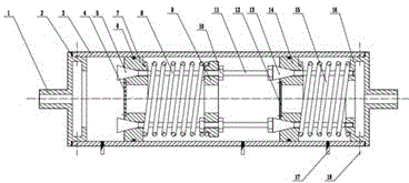
[0019] The present invention is an active detection device for oil pollution degree, which mainly consists of an oil inlet cover 1, a circular shell 3, a filter piston 7 for 15um particles, a filter piston 14 for 5um particles, a return spring 8, 15, and a spoiler 9. Throttle valve rod 11, oil outlet cover 16 and pressure sensor 17 are composed; the present invention is connected in parallel with the oil system to be detected, and the oil to be detected with a certain pressure enters the oil inlet end cover from the oil inlet end cover 1 1. In the closed cavity formed by the circular shell 3 and the oil outlet cover 16, the filter piston 7 with 15um particles first comes into contact with it; due to the action of the return spring 8 between the filter piston 7 with 15um particles and the spoiler 9, The two symmetrically distributed thr...


PUM


Abstract

The invention relates to an initiative detection device for an oil pollution degree. The device mainly comprises an oil inlet end cover, a circular shell, a 15mu m grain filtering piston, a 5mu m grain filtering piston, reset springs, a spoiler, throttle valve rods, an oil outlet end cover and a pressure sensor, wherein the 15mu m grain filtering piston, the 5mu m grain filtering piston and the spoiler are arranged in the circular shell and are connected through two throttle valve rods; two conical valve elements are arranged on the throttle valve rods, and the throttle valve rods are respectively matched with valve holes of the corresponding pistons; and the reset springs are arranged between the 15mu m grain filtering piston and the spoiler and between the 5mu m grain filtering piston and the oil outlet end cover. The obvious change time interval of the pressure value of the pressure sensor is acquired according to the magnitude of the oil pollution degree, and the obvious change time interval is compared with a database result, so that the pollution degree of the to-be-detected oil can be acquired. According to the invention, oil and grain pollutants can be uniformly mixed, filtering cloth is not blocked, the detection operation is simple, the data is reliable and effective, and personal errors are reduced.

Description

technical field [0001] The invention relates to an active detection device for oil pollution degree, in particular to the field of detection of particle pollution in lubricating oil. Background technique [0002] The oil is inevitably polluted by particles inside or outside the system during operation, causing blockage, surface scratches and changes in the physical and chemical properties of the oil-using equipment. In severe cases, it will lead to major production accidents. [0003] Therefore, the effort to study a detection device for the degree of oil pollution has always been one of the key directions in the field of oil control, in order to use a reasonable detection device to detect the pollution degree of lubricating oil in production equipment, and to grasp the pollution of oil used in equipment. It is of great significance to carry out intelligent diagnosis of equipment failures, improve the service life of equipment components, and control oil pollution. [0004]...

Claims


Application Information

Patent Timeline
Patent Type & Authority Applications(China)
IPC IPC(8): G01N15/06G01N1/34
CPCG01N1/34G01N15/0618
Inventor 陈盈洁
Owner 陈盈洁
Why Eureka
Try Eureka