Foldable sample loading arm for sample loading devices

A sampling device, sampling arm technology, applied in the direction of analysis of materials, instruments, etc., can solve the problems that affect the efficiency of sampling, sampling and cleaning, non-professional misoperation, lost steps of rotating motors, etc., to reduce the risk of lost steps , avoid wear and aging, improve work efficiency

Active Publication Date: 2018-10-12
AUTOBIO LABTEC INSTR CO LTD
View PDF7 Cites 0 Cited by
  • Summary
  • Abstract
  • Description
  • Claims
  • Application Information

AI Technical Summary

Problems solved by technology

It can be seen that the sample needle is limited by the fixed circular motion track, so it can only work on the circular track, and the working range is small
When the sampling arm is extended to adapt to the sampling, sampling and cleaning work at a remote location, due to the excessive length of the sampling arm, large volume, and heavy weight, it is easy to cause the risk of losing steps of the rotating motor, and the position of the sampling needle deviates from the preset position , affecting the efficiency of sampling, adding and cleaning, and increasing the cost, especially when the loading arm runs at high speed, this phenomenon is more serious
In addition, the liquid pipeline and circuit cable of the existing sample loading arm are externally installed, the layout is loose, it affects the aesthetics, it is easy to wear and age, and it is easy to cause misoperation by non-professionals, etc.

Method used


Image

  • Foldable sample loading arm for sample loading devices
  • Foldable sample loading arm for sample loading devices
  • Foldable sample loading arm for sample loading devices

Examples


Embodiment Construction

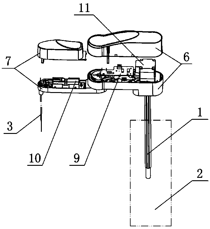
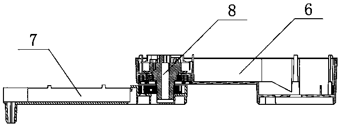
[0017] Such as figure 1 As shown, the foldable sample loading arm suitable for the sample loading device of the present invention includes a sample loading arm body, one end of the sample loading arm body is connected to the sample loading base 2 through the rotating lifting shaft 1, and the other end is connected to the sample loading needle 3 connected. Such as figure 1 , 2 , 4, the sample loading arm body includes the main arm 6 and the auxiliary arm 7, the main arm 6 is connected with the rotating lifting shaft 1, the auxiliary arm 7 is connected with the sampling needle 3, and the intersection of the main arm 6 and the auxiliary arm 7 passes through the rotating shaft 8 connected. In this example, if figure 2 As shown, the main arm 6 is located above the auxiliary arm 7 , and the rotating shaft 8 passes through the intersection of the main arm 6 and the auxiliary arm 7 . Specifically, the upper end of the rotating shaft 8 is sleeved with a bearing, and the bearing f...


PUM


Abstract

The invention discloses a folding type sample adding arm suitable for a sample adding device. The sample adding arm comprises a sample adding arm body. One end of the sample adding arm body is connected with a sample adding base through a rotary lifting shaft, and the other end of the sample adding arm body is connected with a sample adding needle. A pipe and a wire which are led out of the sample adding base are arranged in a through hole in the center of the rotary lifting shaft. The sample adding arm body comprises a main arm and an auxiliary arm. The main arm is connected with the rotary lifting shaft. The auxiliary arm is connected with the sample adding needle. The overlapping positions of the main arm and the auxiliary arm are connected through a rotary shaft. A power mechanism for driving the rotary shaft to rotate is arranged in an inner cavity of the main arm or the auxiliary arm. The wire is subjected to turned-connection in the inner cavity of the main arm through a turned-connection circuit board to reach the rotary shaft after being led out of the rotary lifting shaft, and the wire is sequentially electrically connected with a liquid level detecting circuit board and a sample adding needle electronic element after being wound on the outer wall of the rotary shaft by multiple circles. The sample adding arm is small in size and light in weight, the step loss risk of a motor is relieved, and the accuracy rate of sampling, sample adding, and washing positioning is increased.

Description

technical field [0001] The invention relates to the technical field of in vitro diagnostic equipment, in particular to a foldable sample loading arm suitable for a sample loading device. Background technique [0002] Sampling devices used in biochemical analyzers, chemiluminescence instruments, urine meters, nucleic acids, assembly lines, etc., including sample loading bases, sample loading arms, and sample injection needles. The existing sample loading arm is a separate straight arm, which cannot be folded. One end is connected to the sample loading base through a flower shaft that can be rotated and lifted, and the other end is connected to the sampling needle; the tubes and cables drawn from the sample loading base are from The through hole in the center of the flower shaft is pierced, and then the tube is connected to the sampling needle, and the cable is electrically connected to the circuit element connected to the sampling arm and the sampling needle. When working, t...

Claims


Application Information

Patent Timeline
Patent Type & Authority Patents(China)
IPC IPC(8): G01N35/10
CPCG01N35/1004
Inventor 赵鹏徐灿王超孙隆彭伏光刘聪
Owner AUTOBIO LABTEC INSTR CO LTD
Why Eureka
Try Eureka