Detection device and detection method for binding impedance of display screen
What is AI technical title?
AI technical title is built by Patsnap AI team. It summarizes the technical point description of the patent document.
A technology of impedance detection and display screen, which is applied in the direction of impedance measurement, etc., can solve problems such as cost pressure, bonding process pressure is difficult to control, and large data errors, so as to save labor costs and improve the yield of bonding output.
Inactive Publication Date: 2017-02-22
KUNSHAN GO VISIONOX OPTO ELECTRONICS CO LTD
View PDF12 Cites 11 Cited by
Summary
Abstract
Description
Claims
Application Information
AI Technical Summary
This helps you quickly interpret patents by identifying the three key elements:
Problems solved by technology
Method used
Benefits of technology
Problems solved by technology
At present, the size of COG IC is constantly increasing, and the pressure of the bonding process is not easy to control, resulting in poor module bonding, which leads to uneven bonding impedance, which easily causes excessive bonding impedance, and further causes abnormal screen display
[0006] Experiments have found that if the bonding impedance is too large, it can cause abnormal phenomena such as slightly bright lines and bright lines on the AMOLED display screen, which seriously affects the display quality of the screen and the yield of the output module.
[0007] In the existing technology, the bonding impedance of the production line is tested manually, but the manual test is not only difficult and inefficient, but also has a large error in the test data. When a large amount of statistical data is required, more manpower and resources are required. equipment, resulting in severe cost pressures
Method used
Image
Click on the blue label to locate the original text in one second.
Reading with bidirectional positioning of images and text.
Examples
Embodiment 1
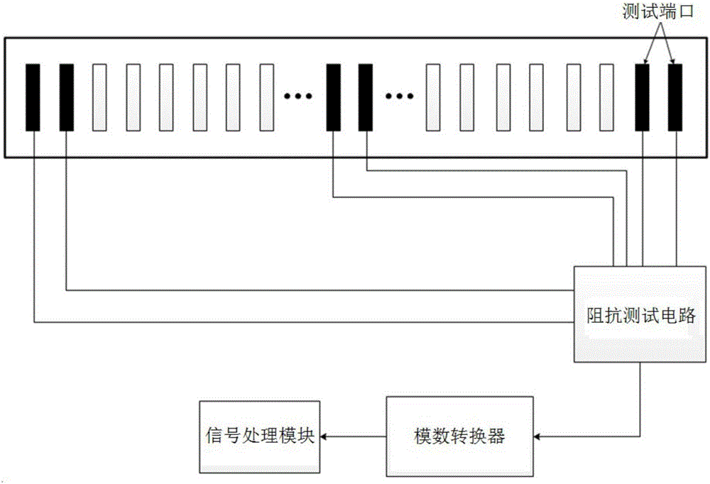
[0037] figure 1 is a schematic diagram of the device of this embodiment. Such as figure 1 As shown, the device includes:
[0038] Test port. The test port is preset at the binding end of the screen, and the impedance between the two test ports is the bonding impedance between the two test ports. The test ports are preferably evenly distributed at the binding end of the screen, and two adjacent test ports form a pair of test ports; when the bonding impedance is uniform, the impedance between each pair of test ports is also uniform.
[0039] Since impedances are to be compared, at least three test ports are required to provide at least two impedance test results for comparison.
[0040] The unit also includes:
[0041] Impedance test circuit. The impedance test circuit is used to test the impedance between the test ports, convert the impedance into an electrical signal and send it to the signal processing module.
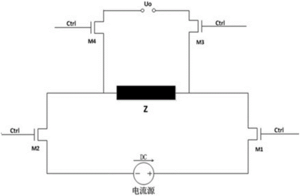
[0042] A typical impedance test circuit such as figure ...
Embodiment 2
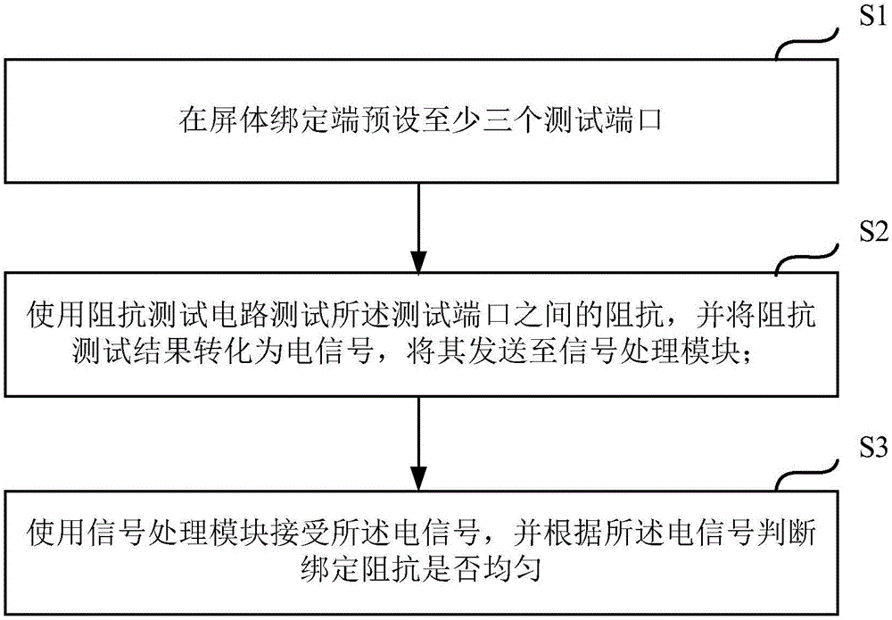
[0051] Based on the detailed analysis above, the embodiment of the present invention also proposes a display binding impedance detection method such as image 3 As shown, the method includes:
[0052] Preset test ports at the screen binding end, the number of the test ports is greater than or equal to three (step S1);
[0053] Use an impedance test circuit to test the impedance between the test ports, and convert the impedance test result into an electrical signal, and send it to the signal processing module (step S2);
[0054] Using a signal processing module to receive the electrical signal, and judge whether the binding impedance is uniform according to the electrical signal (step S3).
[0055] Preferably, in this embodiment, the following method is used to test the impedance between the test ports, and the impedance test result is converted into an electrical signal, which is sent to the signal processing module:
[0056] providing a current source connected to the test ...
PUM
Abstract
The invention discloses a detection device and a detection method for binding impedance of a display screen. The device comprises test ports, an impedance test circuit and a signalprocessing module, wherein the test ports are preset at the binding end of a screen body; the number of the test ports is greater than or equal to three; the impedance test circuit is connected with the test ports and the signalprocessing module; impedance among the test ports is converted into an electrical signal, and the electrical signal is transmitted to the signal processing module; the signal processing module receives the electrical signal, and whether the binding impedance is uniform or not is judged according to the electrical signal. By using the device and the method disclosed by the invention, the impedances at all the positions can be automatically detected and compared, and further whether the binding impedance is uniform or not is judged. Compared with a method for manually testing the binding impedance in the prior art, the detection method disclosed by the invention has the advantages that a large amount of human and material resources are saved, and the binding output yield is also improved.
Description
technical field [0001] The present application relates to the field of electronic equipment, in particular to a binding impedance detection method and device for a display screen of an electronic equipment. Background technique [0002] With the development of the economy, various electronic devices are becoming more and more common in life. Most electronic devices will be equipped with display screens, such as mobile phone screens, monitors, electronic billboards, etc. In order to obtain a better display effect, the requirements for the performance and quality of the display screen are getting higher and higher. [0003] The material used for the display screen is an important factor that determines the performance and quality of the display screen. Commonly used display screen materials include liquid crystal and glass. In recent years, a display screen using an active-matrix organic light emitting diode (AMOLED for short) as a material has emerged, which is called an AM...
Claims
Application Information
Patent Timeline
Application Date:The date an application was filed.
Publication Date:The date a patent or application was officially published.
First Publication Date:The earliest publication date of a patent with the same application number.
Issue Date:Publication date of the patent grant document.
PCT Entry Date:The Entry date of PCT National Phase.
Estimated Expiry Date:The statutory expiry date of a patent right according to the Patent Law, and it is the longest term of protection that the patent right can achieve without the termination of the patent right due to other reasons(Term extension factor has been taken into account ).
Invalid Date:Actual expiry date is based on effective date or publication date of legal transaction data of invalid patent.

